Showing posts with label Projects. Show all posts

Friday, November 22, 2013

Gtk+ Si47xx Radio

Well...it's been a while since I have posted anything. So here is a little teaser of something that I have been casually working on. This is another radio project, this time on a RaspberryPi (RPi) using the same Si4735 chip as my other radio project and using a revamped object oriented design on the Si47xx library. Currently, this Gtk+ GUI you see below runs directly off of the RPi and I use X11 Forwarding to bring the GUI to my local PC, effectively giving me remote control over the radio. But as you can see from the GUI's "Network" menu item. I am in the process of bringing this GUI to the local PC and then remotely connect to a radio server that runs on the RPi. This will be (most likely) a TCP socket where the server will push the RDS/RBDS data to the client and the client will populate the corresponding GUI elements with the received data.


Unfortunately, I am not ready to share the sources publicly, but fear not, this will be made public in the future.

Friday, January 27, 2012

FPGA to 74HC595 Shift Register Module in Verilog

I have had this 74HC595 IC sitting around for quite some time. And earlier this week I decided it was time for me to actually start using it...or at least start learning how I could use it. This chip is a Serial-In Parallel-Out 8-bit shift register that can be used in a variety of ways and it can be cascaded with more of these ICs to create a larger shift register if needed. My plan is to use this newly developed module to act as a low pin count interface between the FPGA and my 16x2 Character LCD module. This will allow me to utilize 4-wires to control the 8-bit parallel interface on the LCD (not including the LCD control lines). This reduced the FPGA pin utilization from 11 pins down to 7 pins...not to shabby. Anyways for those that are interested, the code is linked below. Please note: this module is very much application specific and that it does not enable all practical uses of the 74HC595 IC. For instance, the SRCLR signal is not used and is permanently tied to VCC so that it never clears the register; this of course, may not suit your needs, however the code is heavily commented and adaptation of the code should be fairly simple.


Simulation:
The functional operation of the module can be seen in this timing diagram simulation:

The yellow markers are showing the beginning and end of one complete 8-bit shift operation. This simulation is using a 50ns clock period which is slightly slower than the 24MHz clock that my actual FPGA is using. This simulation shows that it takes about 89 clocks to process a request. 89 clocks at 24MHz is about 3.7us.

Signal Descriptions:

  • RDY: A bit that indicates that the FPGA_2_ShiftReg is idle and is ready to process a request
  • RCLK: A signal sent to the shift register which instructs the output registers to read from the shift register taps
  • SRCLK: A signal sent to the shift register which instructs the 8-bit shift register to shift the register bits and read from the serial input and push it into the LSB.
  • OE: A signal sent to the shift register which sets the output in either Hi-Z (output disabled) or Lo-Z (output enabled). This is an active low signal.
  • SER_OUT: The Serial signal sent to the shift register.
  • CLK: The FPGA's local oscillator which drives the rest of the logic.
  • BYTE_IN: An 8-bit value that is fed into the FPGA_2_ShiftReg module
  • PB: A signal created for simulation purposes to instruct the module to read the 8-bit value from BYTE_IN. Every time this pushbutton is pressed the FPGA_2_ShiftReg module is activated and instructed to read the BYTE_IN. Also the driving module (the module that instantiates and uses the FPGA_2_ShiftReg module) increments the BYTE_IN value by one.


Tuesday, August 2, 2011

Si4735 AM/FM/SW/LW Radio Project

[KEY DOWNLOADS] 


[UPDATE #9] 


Summary of changes specific to Si4735 library:
  • Added support for USE flags. These flags make it quick and easy to strip down the Si4735 library features and will ultimately help you save memory space at the cost of features.
  • Added setProperty and getProperty methods. This will make it very easy for individuals to easily customize the functionality and properties of the Si4735 chip. Consult the Si4735 programmers manual for the register addresses, properties, and acceptable values.
  • Added seekThresholds method to allow the user a quick and easy way to adjust the seek SNR and RSSI thresholds.
  • Added a new field to the Station struct that indicates when the radioText has changed (or is being changed). The radio text is usually left unchanged during a song so this could be used to detect that a new song is playing and you could create an event that triggers off of this flag. This boolean field should only stay high for one readRDS call.
Summary of changes to my project and helper libraries:
  • 'visible' method added to SerLCD.
  • Added a reset baud function to the setBaud method in SerLCD. Issuing setBaud(0) while the splash screen is being displayed will set SerLCD to 9600 baud.
  • Fixed typo in serCommand method in SerLCD library
  • increased stability of sketch by disabling interrupts during callback execution. This should help minimize the frequency of system freeze-up (I don't think it eliminates it completely though).
  • SerLCD is automatically reconfigured to it's maximum supported baud rate of 38400baud. Note there is a known bug where after a cold start-up (arduino completely discharged) that the sketch will not complete the setup process (it will stop at "Loading-Up"). A simple reset will allow it to successfully load.
  • Increased the seek process' sensitivity. It will now detect more "good" quality stations by default.
Si4735 Shield with custom made Logic Level Converter PCB attached


[UPDATE #8] I have updated the library once again. Here is an incomplete list of changes:

  • Updated the code to be compatible with the Arduino IDE v1.0 
  • Added SerLCD.cpp to the repo. SerLCD.h is now an actual class library.
  • Added Rotary_one class library to the repo. This is a single interrupt rotary encoder library. It is not prefect by any means but it is a step in the right direction. Freeing up pin 2 means I can start working on utilizing the Si4735 interrupt capabilities. The original rotary encoder library is left untouched and the two are interchangeable. By default the original is still being used, but in the future, I plan on fine tuning this library so that it is as responsive as the old one, but I have no plans on when that may be.
  • Made minor adjustments to my Si4735_Advanced_Radio project to address a few minor bugs. Audio quality will be slightly cleaner on stations that don't have RDS/RBDS program services. I was constantly writing on the UART line in these circumstances, which created unnecessary noise.


[UPDATE #7] My advanced radio project file is now included under the examples section of the Si4735 library repository. I also made a small update to the library to adjust the deemphasis to the proper levels depending on the region/locale you have specified when calling the setLocale method.


[UPDATE #6] I have finally made my radio project public! For now you can download my pde file and the accompanying libraries (with exception to the Si4735 library which you can just grab the normal way) in my GitHub downloads section. I am still trying to learn how to add files to an existing fork'ed repository, but once I figure that out, I will be adding these files to the "examples" folder in the Si4735 repo. If you have any questions pertaining to this project please let me know. I tried my best to comment most of the code without being overly verbose so some stuff is bound to cause a few people to scratch their heads.


Hopefully this example will provide users with enough insight on how "one" might use the different features that exist in the library.


I still have plans to add USE_FLAGS (as described in the previous update) but I have been busy with other things at the moment.


[UPDATE #5] The Si4735 library has been updated again, here are some of the changes:

  •  Added the retrieval of the UTC month, day, and year(2-digit). Note the hour and minute that are provided in the "Today" structure are local values and not the UTC values. This may change in the future.
  • Fixed the hour and minute computation. These were being incorrectly computed due to a couple mathematical errors.
  • Compacted the Program Type lookup tables into one large LUT. This reduces redundancy and ultimately saves space.
  • Added a private function that helps filter out non-printable characters from strings that are meant to be printed.
I have been playing with the idea of adding in USE_FLAGS to enable/disable the various RDS/RBDS features. I think this might be useful for individuals that want to minimize their memory footprint and compile only the portions of the code that are actually being used. Just a thought...

    [UPDATE #4] This is a quick update to show my audio amplifier circuit at work. I decided against throwing in a preamp into the mix and just went with an LM386N-1. The audio quality is very nice considering the parts being used. There is a little bit of audio clipping occurring when I set the audio at 100%, which I imagine I can eliminate by swapping out my 9V regulated DC adapter with a 12V regulated DC adapter. The speaker that I used was one of my car's old stock speakers. I plan to make another identical circuit so that I can get stereo output, but before I get into that, I will need to start thinking of an enclosure to start housing this stuff.


    Also, one thing I forgot to show off last time was my scanFreq Labview program that communicates with the Arduino and runs through a series of tuneFrequency() and getRSQ() calls. The program takes the SNR information acquired from the chip and plots it versus frequency. This is makes for a very basic spectrum analyzer over the FM frequency band. I would not rely on the metrics too much but they certainly give you a general idea of what to expect for sound quality when tuning to a particular frequency.


    For those interested in this you can download it here: download (note: make sure to change the REFRESH/HOLD button to REFRESH when you want to reacquire the data. HOLD will simply maintain the current data)
    The code essentially expects comma separated values (see the code below for the exact form of the output). The function below will interface with the Labview code perfectly (assuming you define your Si4735 class as "radio" and that you are using my latest version of the library). 


    [UPDATE #3] I got around to updating the Si4735 library. BE WARNED, this update WILL BREAK YOUR CODE...however, in my opinion this update is a necessary step forward and future updates will be less painful for both the users and the developers. Here is an incomplete list of changes and additions:
    • Created a Metrics structure, making the getRSQ method a lot simpler to interface
    • Created a Station structure, making the getRDS method a lot simpler to interface
    • Created a getTime method and a Today structure which acquires the station's local time (eventually this will also include the date, but currently it only contains the 24-hour time). Note this data field is rarely transmitted (most stations send time/date information about 1 time a minute)
    • Removed unused return values (mainly to clean up the code)
    • Added the ability to set (and get) the "locale" (setLocale) to either NA (North American) or EU (European). This effectively sets the look-up table to use for the Program Type.
    • Added setMode and getMode methods. The setMode method calls the "end" method which effectively powers down the Si4735 and the changes then mode. The user is responsible for calling the "begin" method again.
    • Added the interpretation/conversion of the PI field to a Callsign. It seems that not many stations (atleast where I live) use this field. The callsign is the 4 (or 3) letter identification assigned/used by radio station, such as WHEB or KHNN. Note: 3 letter stations are currently not supported in this code but it is on my list of TODOs.
    This was a rather large update and if something doesn't seem quite right please let me know, as I could have forgotten to change something when I went to update the repository.

    My next update will be a small one which is to enable the "date" field in the Today structure. This date field will contain the current year, month, and day.

    Also as a side note, I will be providing access to my Arduino Sketch in the near future.  This will probably be at the same time I perform the above mentioned update to the library


    [UPDATE #2] Here is another update showing performance improvements and added features such as showing the Program Type field (PTY). I have also added a getRSQ method to the library that can be used to get the "Received Signal Quality" of the tuned station. This method provides the following metrics:
    STBLEND - Percent Stereo Blend [0 = Mono, 100 = Stereo]
    RSSI - Receive Signal Strength Indicator [0 - 127 dBuV]
    SNR - Signal to Noise Ratio [0 - 127 dB]
    MULT - Multipath [0 = No multipath, 100 = Full multipath]
    FREQOFF - Signed Frequency offset
    For those interested in accessing the library that my code is running off of (for the most part...there are some minor differences), you can head over to: github Si4735. This is a fork of Trunet's repository with some additions, tweaks, and minor bug fixes.


    [UPDATE #1] Below is a video update to my project. I have now added RDS/RBDS support to my project as well as a LabView interface for controlling the device through the USB/COM port.


    ORIGINAL POST


    I recently acquired an Arduino board and I have found that it is at least 100 times easier to develop/design projects than an FPGA. Don't get me wrong I still prefer FPGA (I feel like I am more in control of what I do), but programming hardware from a C/C++ level is so much easier in comparison to HDL programming. This fact, coupled with the fact that the Arduino is an open source, driven community, hardware/software platfrom makes for a very user friendly environment. 

    Anyways, I decided to jump into the realm of Radio by using Sparkfun's  Si4735 Shield. The Si4735 is a pretty impressive chip that has a lot of functionality in a small form factor. Check out the video and see the basic block diagram of this project. When I get around to it, I will provide more details here.

    Things that need improving:
    1. You might have noticed in the video that the rotary encoder had an issue when I was attempting to change the frequency in "stepped" mode. This is a bug that currently only exists while in this mode. I am not sure if the underlying cause is my rotary encoder's debouncing algorithm or if it is some weird timing issue. This was fixed via modification to my rotary encoder callback procedure
    2. The rotary encoder's debouncing algorithm also needs improvement, while the performance is reasonable, it is far from perfect and needs some fine tuning. Updating my code and cleaning up my wiring helped a lot.
    3. There appears to be an issue with using a power source connected to the Arduino's external power jack (instead of using the USB's supplied power). The SPI interface becomes a little unreliable.
    Overall though this project, when powered from the USB port, is very reliable and user friendly. I have a few neat ideas for adding onto this project that I will share at a later time. The performance of the Radio shield is very good considering that the FM signal that I was receiving were coming from the line out (that is wired to my amplifier and speakers), and the audio quality was exceptional. 

    Saturday, June 25, 2011

    GPS to 16x2 Character LCD Using an FPGA


    This is a project that uses a Spartan-3E FPGA Board (Xylo-LM) to grab the serial stream transmitted by a Locosys LS20031 GPS Module and parse the messages for the latitude and longitude. The latitude and longitude values are then feed into a 16x2 Character LCD display on a push of a button.

    Note: The GPS coordinates shown will not lead you to me. The GPS module at the time of recording this, was not locked onto my coordinates...so don't try hunting me down..else you will find yourself in the Atlantic =P

    Below is a basic block diagram that helps to illustrate what the FPGA does in the system. The FPGA has 3 modules: A Serial Module, a Parser Module, and an LCD Controller Module. The serial module is only responsible for acquiring the serial data at the specified baud rate. Over sampling is used in the FPGA to help minimize bit errors.  The serial module passes the raw data to the parser module. At this point in time the raw data is the NMEA messages (with the overhead information removed, i.e. stopbit/startbit). The parser module waits for the occurrence of a '$' which indicates the start of an MTK/NMEA message. Once the '$' is received, the parser extracts the message type and checks for a "GGA" message. If the current message is a GGA message, then we extract the Latitude and Longitude based on the standard format of the GGA message. This is currently being done by counting the characters; however, counting the comma delimiters work just as well. The parser module passes the latitude and longitude data to the LCD module as it is received on the serial line. The LCD controller module handles the initialization process required to set the LCD module into an operative mode, and it handles all the timing and writing data to the display.


    This is an on-going project and I plan to add many more features to it. Below are some changes that I plan on making in the future.

    Future Improvements/Additions:

    • Write the serial stream from the serial module to a Block Memory or RAM
    • Read the data in a Block Memory or RAM and feed the data into the Parser Module.
    • Perform mathematical operations on the acquired data, such as computing the displacement from the current location to the last saved location.

    For those interested in knowing more about this project, or want more information about certain aspects of the HDL code that I wrote, please don't hesitate to post a comment.

    For those interested in the LCD controller module's code, go here: LCD Controller.
    Or to download all of the related HDL files, go here: GPS2LCD_Files.zip

    My project was featured on Sparkfun's Main Page! Pretty cool and I got some good constructive criticism.

    Thursday, May 19, 2011

    Using an MCP3002 ADC for Interfacing an FPGA with a Photocell

    The MCP3002 ADC Chip is a very handy device. You can interface with it via a very simple SPI (Serial Peripheral Interface) protocol. The Verilog module that I designed to interface with this chip works beautifully.

    The module I created uses both channels of the MCP3002 in an "interlaced" single-ended mode. The module is strictly configured to work with a local oscillator of 24MHz, but minor adjustments to the process that converts the local clock to a 1.2MHz clock is all that needs to be modified. The 1.2MHz clock is the maximum frequency that the IC can operate at while powered at 2.7V as specified in the datasheet (pg3) under the "Timing Parameters". In my case my FPGA uses 3.3V logic so Fclk(max) should reside somewhere between this and 3.2MHz. If we assume a linear relationship between voltage and operating frequency, then the maximum expected operating frequency at 3.3V would be ~1.688MHz, thus operating at 1.2MHz "should" be a safe level of operation while pushing the IC to work at its maximum.

    As far as the code goes, it is really self explanatory. I would recommend anyone that is attempting to use this code to have a copy of the datasheet on hand so that you can see the relationship from my code and the datasheet's timing diagram. Figure 5-1 was specifically used to design this Verilog Module.

    On a hardware interfacing note, be sure to pay attention to Figure 4-2 in the datasheet, this clearly states that the ADC's CH0 and CH1 input signals NEED to be buffered (i.e. use an opamp in a buffer configuration or similar). If you skip this, your maximum operating frequency will be lower that the one defined in the datasheet.

    The code that I provide here is free to use however you would like, but I would appreciate it if you give me credit for my work. Also constructive criticism is welcome, if you see something that could be done better another way, let me know.

    Download: MCP3002 ADC Module

    Tuesday, January 26, 2010

    Schematics for AngelBot - A Light Following Robot

    So, I have been quite lazy as of late. This project has been sitting around at "near completion" for about 2 months. So I figure it is about time I post some of the schematics and parts used to make this Robot. As of right now this robot is completely wired up and inferaced to my FPGA; however, I am still "working on" getting the light steering circuit working properly in the code.

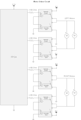
    Here are the schematics:

    The "Motor Driver Circuit", does what it sounds like...it drives the motors; this circuit is used to interface the FPGA logic with the motors. Since the motors demand a significant amount of current to drive them (much more than the FPGA can provide), relays were used to create an interface between the logic and the motors which allows the motors to operate at full speed. Each side (left and right) are individually controlled via two SPDT relays. The relays used below are actually Dual SPST optical relays, but they can easily be wired up for SPDT operation. The NC (normally closed) state pushes 6V through the positive motor terminal which then goes to ground. The NO (normally open) state pushes 6V through the negative terminal which then goes to ground. An alternative H-Bridge Integrated Circuit could have been used to drive the motors; at the time of designing this circuit, I did not know of H-Bridges...but it turns out that is exactly what I designed! Catch Diodes may also be used to allow for additional protection and efficiency (but really are not needed in this implementation). Catch Diodes allow for a path for the electromagnetic field stored in an induction motor to deplete. These catch diodes are usually "schottky diodes" which are fast switching, low forward voltage diodes. These diodes are placed across each switching mechanism (i.e. transistor) in reverse bias configuration.
    The "Collision Avoidance Circuit" is used to sense objects that are in close proximity and then steer away from the object. Infrared Proximity Sensors are used to acquire an analog voltage signal that is compared to a reference voltage that acts as the decision making device. These two IR sensors are mounted in front of the robot and are used to steer left or right. The third comparator in the circuit (in the middle), is used to make a decision as to which sensor detects a closer object. This third comparator will allow the robot to make an intelligent decision as to which way it should turn if a person or some non stationary object gets close to the robot.


    The "Light Steering Circuit" is used to give the robot an objective other than avoiding collisions. When there are no objects being detected by the IR sensors, the Light Steering Circuit kicks in and guides the robot to locations containing high light intensity. In the future, I hope to addon to this robot and have a rechargable battery that is being powered by a photovoltaic cell. This circuit uses simple photocells to measure the light intensity. Again the robot uses stereoscopy to determine direction. A 10-bit ADC that communicates with the FPGA via the SPI (Serial Parallel Interface) protocol is used. The ADC wants a low impedance input, but doing so would cause problems with the photocell's voltage divider circuit being loaded down (effectively bypassing the 23K Ohm potentiometer), this means we need a buffer to create an intermediate stage that has a high input impedance and low output impedance.
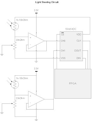
    The parts used are:

    KNJN XYLO-LM FPGA board (used as the logic/brains of my robot). This is an EXPENSIVE piece of hardware, and I would NOT RECOMMEND getting this if you want to build a similar robot. There are much cheaper chips out there (i.e. PICS or even just a bunch of logic gates with a 555 timer chip) that can do the same thing this is doing. The only reason why I used an FPGA was because I already had the board and wanted to start another project with it.
    http://www.knjn.com/ShopBoards_USB2.html

    Mini Photocells (two of these are used in stereo to find the most intense lighting)
    http://www.sparkfun.com/commerce/product_info.php?products_id=9088

    10bit Analog-Digital Converter MCP3002 (used to acquire samples from the photocells)
    http://dl.dropbox.com/u/767596/Resources/ROBO/21294C.pdf
    I needed this 10-bit ADC versus a comparator because I wanted the robot to maintain going in a certain direction until there was a significant difference between the two photocells, otherwise the robot would constantly be turning left and right. This "difference parameter" is defined in my FPGA code. Eventually, I want to control this parameter through a Rotary encoder (which is basically a digital POT).

    LM339 Quad Comparators (used as the decision making device for the obstacle avoidance system)
    http://www.radioshack.com/product/index.jsp?productId=2062593

    LM358 OpAmp (used to buffer the photocell signal, and make a high input impedance, low output impedance stage that goes into the 10bit ADC)
    http://dl.dropbox.com/u/767596/Resources/ROBO/LM358.pdf

    3.3 Voltage Regulator (used to power my FPGA board and some other components that want 3.3V instead of the 6V from my battery pack)
    http://dl.dropbox.com/u/767596/Resources/ROBO/LD1117V33.pdf

    Sharp IR Proximity Sensors (used to avoid obstacles by using two of them in stereo, and also used two additional sensors, one points down at the rear end and one pointing down at the front to avoid falling down a ledge)
    http://dl.dropbox.com/u/767596/Resources/ROBO/GP2Y0A21YK.pdf
    What's interesting about this sensor is the Voltage vs. Distance curve. Since the peak output voltage is at 6cm or so, and it drops off both as you increase and decrease in distance, I was able to split this curve into two sections. The 0-6cm range is used as the "drop-off detection" where I used the logic: if the distance is less than X cm away keep the motors in the default state, otherwise go into reverse. The 6-80cm range was used for the "object-avoidance circuit" that helped steer the robot when an object was in a defined range.

    Wheel Encoders (used to track the wheel rotations, not actually implemented into my design yet)
    http://www.sparkfun.com/commerce/product_info.php?products_id=9208

    Micro Metal Gearmotor 100:1 (I use 4 of these motors, which enables the robot to have enough torque to go on carpet)
    http://www.sparkfun.com/commerce/product_info.php?products_id=8910

    SPDT Relay Switches (These are photo relay switches, so they don't even make the clicking noise. I use these to drive the motors from the 6V and GND supplies. I use 6V-->GND for the forward drive and the GND-->6V for the reverse drive)
    http://dl.dropbox.com/u/767596/Resources/ROBO/ps7122a1c.pdf

    Pictures, videos, and HDL code to come later!