Are you interested in Digital Image Processing (DIP), but don't know where to start? Well, I have good news there are two routes that just might suite your needs. First is Matlab's Toolbox for Image Processing. The DIP Toolbox is a very powerful set of commands that will make image processing as easy as pie. Not to mention that Mathworks has excellent documentation on all its functions. However this might not be an option for some, since it does cost money if your university doesn't have access to it.
The other highly regarded option is to get OpenCV. OpenCV is the "Open Computer Vision" library written in C, meaning maximum performance. This library was originally created and developed by Intel Corp. which focused on optimizing the code as much as possible, and I have to say, they did a very good job, however, doing certain tasks that you take for granted in Matlab might not be an easy task for OpenCV and C/C++. If you want to learn more about OpenCV, I suggest using the Yahoo! Group called OpenCV. This group is a very active community of imaging experts and novices that discuss anything OpenCV/imaging related. There is also a very nice book by O'Reilly that serves as an aid in learning OpenCV. Here are some links that I have found useful for OpenCV:
http://tech.groups.yahoo.com/group/OpenCV/?yguid=361088785
http://opencv.willowgarage.com/wiki/wiki-static/
http://www.seas.upenn.edu/~bensapp/opencvdocs/
http://www.cs.iit.edu/~agam/cs512/lect-notes/opencv-intro/opencv-intro.html
Friday, July 17, 2009
Thursday, July 16, 2009
Computer Architectures: Neurocomputing Presentation
Do you have an interest in neurocomputing architectures, or want to get some basics on neural networks? Check out the presentation I had done in Fall Semester 2008, where I presented on a couple papers that focus on neurocomputing architectures using FPGAs.

Topic #2 (Part2): Matlab GUI Callbacks
Last time we discussed the very basics of Matlab GUI. We learned what "handles" are and some of the primary functions that one would use to interact and gain additional functionality from a handle. In this section, I would like to discuss callback functions. Callback functions are a very important element to GUI programming. One of the key mindsets to GUI programming is to understand that they are "event-based" programs. Event based programs are programs that if left untouched do absolutely nothing, the only time when they execute functions is when the user interacts with it.
As we discussed last time there are some very fundamental functions that we must understand to use a graphical object. One of the is the "get" function. Say we create a window that contains a pushbutton by using the following code:
h=figure(1);pb=uicontrol('Style', 'pushbutton');
Not much going on in the above statements. If we want to give the pushbutton some task to do, we would want to specify the callback function. To see all the attributes that can be set on the pushbutton, issue the command:
get(pb)
Which will return something like this:
BackgroundColor = [0.941176 0.941176 0.941176]Callback =CData = []Enable = onExtent = [0 0 4 4]FontAngle = normalFontName = MS Sans SerifFontSize = [8]FontUnits = pointsFontWeight = normalForegroundColor = [0 0 0]HorizontalAlignment = centerKeyPressFcn =ListboxTop = [1]Max = [1]Min = [0]Position = [20 20 60 20]String =Style = pushbuttonSliderStep = [0.01 0.1]TooltipString =Units = pixelsValue = [0]BeingDeleted = offButtonDownFcn =Children = []Clipping = onCreateFcn =DeleteFcn =BusyAction = queueHandleVisibility = onHitTest = onInterruptible = onParent = [1]Selected = offSelectionHighlight = onTag =Type = uicontrolUIContextMenu = []UserData = []Visible = on
As you can see, "Callback" is not set to anything by default. Lets say we want it to compute x=sqrt(2) whenever we push the button. There are two ways we can set the callback.
Generally, the best way to handle a callback function is to make a function that does what you want the callback to do. In this case we would make and save a function like:
function rootTwosqrt(2)
And we would set the callback using:
set(pb,'Callback',rootTwo);
To make things even more trackable in your code you could make a single function that contains all the callback functions. For example, if you make a callback function called callbackFcn you could do this:
function callbackFcn(ID)switch IDcase 1disp('ID=1, pb1 pressed...')sqrt(2)otherwisedisp('Incorrect Callback ID...')disp('Doing nothing.')end
And you would set the Callback with the specific ID you want the function to be passed:
set(pb,'Callback',callbackFcn(1));
However, since this is such a simple task, instead of making another file that can make it difficult to navigate through your code, you may want to just emmbed that function into the callback string. This can be done using:
set(pb,'Callback','sqrt(2)');
Note: that if the function you are trying to use contains a string and you want to embed the function inout the callback string, then you need to use a second quotation for every single quote in the statement. For example, if I want to use the statement below in my callback:
x=['abc,'def'];
The I would have to use the "set" function like this:
set(pb,'Callback','x=[''abc,''def''];');
These second quotation marks act as a sort of "escape character" that prevents the callback function from being misinterpreted.
I think this is all I will discuss about callback functions for now. But be sure to use the "Product Help" in Matlab (search for uicontrol properties) to get more information.
But before I conclude this post I want to discuss two properties that are sort of overlooked by the average user. When you get more advanced in GUI design using Matlab, it isn't uncommon to have 100 handles that you need to interact with. Managing these handles can be a nightmare if you done understand some of the options that Matlab has set forth for such occassions. Two of the most useful properties that can be used are "Tag" and "UserData". The "Tag" is generally understood to be a unique name to that uicontrol. Say for instance you have three pushbuttons, it might be logical to give them Tag names: "pb1", "pb2", and "pb3". What this does is it gives the user a means to find a handle that a function does not have stored locally in its memory space. This is where the power of the function "findobj" comes in. Findobj takes in a couple arguments, the first is a property name and the second is the corresponding property value to look for. If I want to find the handle of the pushbutton with the Tag='pb2', I would issue the command:
findobj('Tag','pb2')The second and more interesting property is the 'UserData' property. Matlab documentation says that this has no inherent function or purpose, so what we can do is exploit this and use it as a sort of heirarchy for graphical objects. Say you have several objects that you would like to operate on in the same exact manner. Instead of individually referencing their unique Tag names you can make a group name using UserData. If I want pb1, pb2, and pb3 to all get set to invisible it might be nice to group them first so that in the future the number of statements I have to code are reduced. Here is a full example of how one could use UserData:
uicontrol('Style','pushbutton',...'Tag','pb1',...'UserData','pbGroup');uicontrol('Style','pushbutton',...'Tag','pb2',...'UserData','pbGroup');uicontrol('Style','pushbutton',...'Tag','pb3',...'UserData','pbGroup');handles=findobj('UserData','pbGroup');for i=1:length(handles)set(handles(i),'Visible','off');end
This is a very primative example but it should get the point across that you can keep using Tags to individually reference a handle and you can use UserData to reference a collection of handles. You can even get fancy with the UserData and have a function that reads the UserData and checks to see if an object belongs to more than one grouping and operate on that object accordingly.
I think this is enough for now. Eventually, I will post a videoclip that will showcase some GUIs that I made that use the features I have outlined above.
Tuesday, July 14, 2009
Topic #1 (Part 5): HDL - User Constraint File
If everything has been working out for you then you are probably ready to test the HDL code on a real device. But before we can generate the binary file used to program the FPGA we need to tell Xilinx ISE exactly how to connect the I/Os to the FPGA.
Xilinx ISE generates an optimal solution for the internal wiring; technically you can be a terrible coder yet at the end of the day if the code compiles, then it will work just like any other code designed to do the same task. The reason for this is that ISE detects all unused bits, signals, variables, and removes them from the physical implementation. The one thing that ISE can't determine on its own from the HDL code, is how the module's I/O ports connect to the physical FPGA pins. This is where the UCF file comes in. The UCF, or User Constraint File, is a file that lists the module's port mappings to the physical FPGA pins. The most generic form of a UCF statement is as follows:
NET "PORT_NAME" LOC = " PIN_NAME"; # COMMENTS HERE
A UCF statement always starts with NET and ends with ";"; comments can be used by using the the hash symbol "#". The PORT_NAME variable should be replaced with one of your module's ports. For instance, the most common port name would be the clock. In our previous posts we have been using a module that was defined as:
module dff(clk,d,q,qn);
This means that we will need exactly 4 NET statements. This will lead us to:
NET "clk" LOC = "PIN_NAME"; # Clock signal, 24MHz oscillator NET "d" LOC = "PIN_NAME"; # Data input signal, a pushbutton NET "q" LOC = "PIN_NAME"; # Output signal, an LED NET "qn" LOC = "PIN_NAME"; # Inverted output signal, an LED
So the above preps us for how the module will interact with the FPGA board. I have an FPGA board with a 24MHz oscillator, a pushbutton switch, and a couple LEDs, all of which will interact with this code. The next step would be to specify the location that these ports will be mapped to on the physical FPGA. This is done by using the keyword LOC and replacing PIN_NAME with the pin name that your FPGA uses. To determine what the pin name is, you can either look in your FPGA's documentation or you can look on the board's silkscreen as they most likely label them correctly on the board. Below is a picture of the board I am using (from KNJN.com).


As you can see, the pins, LEDs, and pushbutton are all labeled; it is generally a good idea though to skim through your documentation first as there could be silkscreen errors that would cause you to map a port to the wrong pin. Also, some FPGA boards want additional parameters other than just the NET and LOC. These parameters can be attatched by using the "|" character . One common parameter that you might define is the IOSTANDARD as can be seen below:
NET "LED" LOC = "p146" | IOSTANDARD = LVCMOS33 ;
In the case above, the IOSTANDARD is set to a low-voltage CMOS (3.3Volts). Your board may differ so make sure to consult your board's documentation. The final UCF file for my board using the dff module is:
# Clock
NET "clk"  LOC = "p181" | IOSTANDARD = LVCMOS33 ;
# Pushbutton
NET "d"  LOC = "p148" | IOSTANDARD = LVCMOS33 ;
# LED
NET "q"  LOC = "p146" | IOSTANDARD = LVCMOS33 ;
# LED
NET "qn"  LOC = "p147" | IOSTANDARD = LVCMOS33 ;
Now that we have the UCF we can continue with generating the bit file. To do this all you need to do is double click on the "Generate Programming File" inside the Processes window. It will first Synthesize the HDL code and check the syntax, then it will implement the design (check for any physical routing problems and check the UCF) and then generate the bit file.
Once the bit file has been generated we are ready to launch iMPACT. Stay tuned for more...
Monday, July 13, 2009
FPGA4FUN
Want to start learning more about FPGAs? Check out fpga4fun.com
This site will cover lots of small projects for FPGAs ranging from the basics to very advanced projects that involve state machines.
Also check out KNJN which is a website that accompanies FPGA4Fun that sells their FPGA boards. They carry really cheap, small, low-power FPGA boards. My next post on HDL will show case one of their high-end boards.
Topic #1 (Part 4): HDL - Simulation
Ok, so say your HDL design did not work out as planned. What can you do? Well, it turns out there are several options. The first and most primitive method is to physically interact with your FPGA and try to determine what the root cause of the bug is. Maybe you decide to slow down the input clock to your system and turn on a few LEDs as indicators of important variables.
The second and most advanced method is to implement a Chipscope "core" on your FPGA. Chipscope is a program Xilinx offers that allows you to physically analyze HDL code directly on your FPGA. Unfortunately if you want this feature you will have to dish out some cash, as it is licensed. But the really nice thing about it is the fact that it gives you the "actual" results as apposed to the third option below. A "core" is an IP (intellectual property) that you can instantiate into your HDL code to give the FPGA additional functionality. Think of cores as mini-programs for your FPGA.
The third and last method is to simulate in software. A major plus is that Xilinx and Altera provide these features for free. To simulate, you need to design what is called a "testbench", testbenches are additional snippets of HDL code that stimulate the input signals (i.e. clock signals) such that the actual HDL code that you are trying to test has a clue as to when and how frequent to update signals and registers.
I will give you a step by step procedure for setting up a testbench in Xilinx ISE using the previous dff (D Flip Flop) HDL code, which I re-posted below for clarity.
It should be noted that it DOES NOT matter which variant you choose for your HDL code (i.e. Verilog or VHDL). As long as the I/O ports and variables are the same you can simulate the exactly the same way.
Step 1: Add the testbench module.
You have the choice to add a VHDL testbench or Verilog testbench. Choose which ever one you are more comfortable with. To do this you:
Step 2: Add the stimulation code
By definition all inputs will need some stimulation and all outputs, registers, signals need to be initialized. To do this you will need to do something like this:
This is one of the most basic clock generation schemes you can use in a testbench. The "#" is a "WAIT" operator that waits a period of time until executing the next sequential statement.
Step 3: Simulate
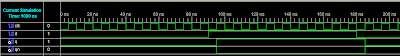
Now that the test bench has been coded, we can now move on to the actual simulation! To simulate, go to the "Processes" window and select the "Processes" tab if it isn't selected already and double click "Simulate Behavioral Model". If all went according to plan, you will see some output in the console window and a plot of a nice timing diagram as seen below.
 If you see some of your signals crossed out such that you can't observed their transitions, then chances are you have not initialized some registers in your primary HDL code. If a signal depends on another signal that has not been set to an initial value, then the simulation will not be able to determine a starting point. The interesting part about this is that this does not matter to a physical system. Most systems will assume a logic low or high upon power up.
Hopefully everything went to plan and you have a working simulation of your DFF. There is a lot to the simulation that I did not explain or touch, go ahead and explore what other functionalities the simulator contains.
The second and most advanced method is to implement a Chipscope "core" on your FPGA. Chipscope is a program Xilinx offers that allows you to physically analyze HDL code directly on your FPGA. Unfortunately if you want this feature you will have to dish out some cash, as it is licensed. But the really nice thing about it is the fact that it gives you the "actual" results as apposed to the third option below. A "core" is an IP (intellectual property) that you can instantiate into your HDL code to give the FPGA additional functionality. Think of cores as mini-programs for your FPGA.
The third and last method is to simulate in software. A major plus is that Xilinx and Altera provide these features for free. To simulate, you need to design what is called a "testbench", testbenches are additional snippets of HDL code that stimulate the input signals (i.e. clock signals) such that the actual HDL code that you are trying to test has a clue as to when and how frequent to update signals and registers.
I will give you a step by step procedure for setting up a testbench in Xilinx ISE using the previous dff (D Flip Flop) HDL code, which I re-posted below for clarity.
module dff(clk,d,q,qn);
input clk, d;
output q, qn;
reg q=0;
reg qn=1;
always @(posedge clk)
begin
  q<=d;
  qn<=~d;
end
endmodule
It should be noted that it DOES NOT matter which variant you choose for your HDL code (i.e. Verilog or VHDL). As long as the I/O ports and variables are the same you can simulate the exactly the same way.
Step 1: Add the testbench module.
You have the choice to add a VHDL testbench or Verilog testbench. Choose which ever one you are more comfortable with. To do this you:
- Right click on your module name in the "Sources" window with the "Sources for:" set to "Implementation".
- Select "New Source".
- Select either the "Verilog Test Fixture" or the "VHDL Testbench" (I used the Verilog Test Fixture in this example)
- If you have more than one module in your project you will be prompted for which module to associate this test bench with. Select the appropriate one.
- Finish up with the rest of the prompts and Xilinx will make a template for you. It will look like:
module testbench;

// Inputs
reg clk;
reg d;

// Outputs
wire q;
wire qn;

// Instantiate the Unit Under Test (UUT)
dff uut (
.clk(clk),
.d(d),
.q(q),
.qn(qn)
);

initial begin
// Initialize Inputs
clk = 0;
d = 0;

// Wait 100 ns for global reset to finish
#100;

// Add stimulus here

end

endmodule
Step 2: Add the stimulation code
By definition all inputs will need some stimulation and all outputs, registers, signals need to be initialized. To do this you will need to do something like this:
module testbench;
// Inputs
reg clk;
reg d;

// Outputs
wire q;
wire qn;

// Instantiate the Unit Under Test (UUT)
dff uut (
.clk(clk),
.d(d),
.q(q),
.qn(qn)
);

initial begin
// Initialize Inputs
clk = 0;
d = 0;
// Wait 100 ns for global reset to finish
#100;
// Add stimulus here

// Input Generation
#10 d = 1;
#10 d = 0;
#10 d = 1;
#10 d = 0;
#10 d = 1;
#100 d = 0;
#50 d = 1;
#60 d = 0;

// Console Output
$timeformat(-9,1,"ns",12);
$display(" Time Clk pushbutton");
$monitor("%t %b %b", $realtime, clk, d);
end

// Declare a clock period constant.
parameter clockPeriod = 100;

// Clock Generation
initial begin
forever clk = #(clockPeriod / 2) ~ clk;
end

endmodule
- So the code that was added to the testbench achieves several functions that we need/want.
- First, we declare a clockPeriod parameter. You don't necessarily need a clock period parameter, it is mainly to help keep things verbose. Most parameters, if they deal with time, are generally measured in nanoseconds. In this case we created a parameter called "clockPeriod" that is given a value of 100. The value is technically unitless at this point in time but when applied to timing constraints it will gain the unit "ns"
- Next we generate the clock signal. More specifically, we generate the clock edges. First we use "initial begin" to indicate another process that will continually execute each iteration and then follow that with the "forever" keyword. This says that we re-execute the statement after a period of time each iteration. The syntax is a little strange but what this says is:
During each iteration, after clockPeriod/2 nanoseconds take the clock signal and invert it.
This is one of the most basic clock generation schemes you can use in a testbench. The "#" is a "WAIT" operator that waits a period of time until executing the next sequential statement.
- By using the wait operator we can make a more interesting signal for the input signal d (instead of using a periodic signal). By using a sequence of these wait statements followed by d=0; and d=1; statements, we can create any sequence we need to help prove that the code is working as expected.
- The last thing that we might want to add is some output to the console window that gives you the results in text format. To do this we use console functions by using the console operator "$". There are many functions that you may want to use, in this testbench, I used $timeformat, $display, and $monitor. The $timeformat function allows you to specify the format of the realtime simulation, $display allows you to output text to the console, and $monitor allows you to output simulation variables to the console window.
Step 3: Simulate
Now that the test bench has been coded, we can now move on to the actual simulation! To simulate, go to the "Processes" window and select the "Processes" tab if it isn't selected already and double click "Simulate Behavioral Model". If all went according to plan, you will see some output in the console window and a plot of a nice timing diagram as seen below.
 If you see some of your signals crossed out such that you can't observed their transitions, then chances are you have not initialized some registers in your primary HDL code. If a signal depends on another signal that has not been set to an initial value, then the simulation will not be able to determine a starting point. The interesting part about this is that this does not matter to a physical system. Most systems will assume a logic low or high upon power up.
Hopefully everything went to plan and you have a working simulation of your DFF. There is a lot to the simulation that I did not explain or touch, go ahead and explore what other functionalities the simulator contains.
Coming up shortly, I will discuss how to create the "ufc" file, generate the "bit" file, and program your FPGA in iMPACT.
Wednesday, July 8, 2009
Topic #1 (Part 3): HDL - VHDL
Well, I suppose I should get back to the first topic concerning HDL. We left off discussing the basic syntax of Verilog. Now I would like to create the same dff module in VHDL so that we can compare the two. Below is the module, or as it is called in VHDL, the architecture:
The first 4 statements describe typical libraries that Xilinx ISE uses when you create a new VHDL module. Technically in this specific design the first two would only be needed as we are not doing anything with unsigned or arithmetic operations.
VHDL breaks the code into two sections, an "entity" and an "architecture". The job of the entity is to define the I/O ports and the data types that are to be use in the architecture. At the top level of the design (commonly denoted as the TLE), these ports are supposed to be physically accessible on your FPGA and are associated with some form of user constraint file (Xilinx called this the UCF) that defines the pin/pad mappings to these ports and additional timing and signalling characteristics/constraints. In other words, if I were to define a counter that is 8 bits long then each of those bits could be be assigned to some physical location on the FPGA (this could be a package pin or a physical locations that is within the FPGA fabric). If you want to use a signal but don't want to physically represent it on your FPGA, then keep reading as I will be briefly covering where this is done. All statements that are to be defined in the entity should be described between the "entity is" (where is the module name that you are using) and "end " statement. To define the ports we must describe them inside a function called "Port();". Inside Port(), we define the name of the ports, the type of the ports (i.e. "in", "out", "inout"), and the data type of the ports. VHDL has a fairly large number of data types to choose from in comparison to Verilog, but in reality there really are only two data types you need, std_logic and std_logic_vector. As the names suggest, one is a single logic bit and the other is an array of logic bits. Below are some other data types that are built into VHDL
After the entity is defined comes the architecture. The architecture defines the underlying function of the VHDL module (in other words, it defines what the module does). The beginning of the architecture is indicated by the keyword "architecture" followed by a name for the architecture this should be unique, by default Xilinx ISE uses "Behavioral" which indicates that the architecture is following a "Behavioral Model". Another common name for an architecture is "Structural" which indicates that a "Structual Model" is being used. This name purely serves to improve readability and understanding of the design as a whole; you could name it whatever you want, but it is recommended that it is an informative name. Note, if you have a design/project with multiple VHDL architectures, you will need to be aware of the name used for each and make sure that each architecture is unique.
After the architecture name is the keyword "of" which followed by the name of some entity; by having this option is allows you to use a single entity to define multiple architectures. So say you have a D Flip Flip, and a T Flip Flip, they both have the same ports but the inner function differs, this allows you to reuse the entity and keeps the code MUCH MUCH cleaner. This reuse of entities and the fact that all the ports are fully defined in a centralized location is one of the key elements that make VHDL nice, especially when it comes time to debug/troubleshoot.
After declaring what entity the architecture is to use, we use the keyword "is". After the "is" you have an option, you can define additional signals to be used that are internal to the architecture or if you have everything you need you can issue the keyword "begin". In this case we don't need any additional signals so we go right into the architecture description.
In VHDL, you define a "process" that indicates that some sort of process is to be executed on an event general caused by a state change of a signal (such as a clock edge). In this case we use "process(clk)" that says that code will be executed during each clock edge. The contents within the parenthesis is generally refered to as the sensitivity list. Multiple signals/nets can be places in the sensitivity list which basically means if any of the nets within the list change then the process fires off; this allows a designer to describe both synchronous and asynchronous systems/processes. Again each process that is defined should be followed by the "begin" keyword. In this design we want to update the D Flip Flop during each positive edge. In Verilog, this was accomplished by "always @(posedge clk)", in VHDL we use the if statement below:
This statement says that whenever the clk changes (which is indicated by clk'EVENT ) AND clk is logic high (which is indicated by clk='1') then we update q and qn. Likewise, if we want to update only on negative clk edges we would just change clk='1' to clk='0'. After the q and qn update we just need to end our "if", "process" and "Behavioral" architecture.
Well there you have it, hopefully you got something out of this VERY VERY brief tutorial of Verilog and VHDL. Which one you choose is a matter of preference; sometimes the module is easier to code in Verilog other times it is easier to code in VHDL. VHDL is generally seen to be much more powerful, but it is also very strict in when and where you declare/instantiate signals or other modules.
Coming up next time, I will discuss how to create the bit file to physically program a Xilinx FPGA, how to physical map I/O ports to FPGA pins using a "ucf" file, and how to simulate your design using a testbench.
library IEEE;
use IEEE.STD_LOGIC_1164.ALL;
use IEEE.STD_LOGIC_ARITH.ALL;
use IEEE.STD_LOGIC_UNSIGNED.ALL;

entity dff is
Port (     clk, d: in  std_logic;
            q, qn: out std_logic);
end dff;

architecture Behavioral of dff is
begin
process(clk)
begin
    if clk'EVENT and clk='1' then
       q<=d;         qn<=not d;      end if;     end process; end Behavioral;
The first 4 statements describe typical libraries that Xilinx ISE uses when you create a new VHDL module. Technically in this specific design the first two would only be needed as we are not doing anything with unsigned or arithmetic operations.
VHDL breaks the code into two sections, an "entity" and an "architecture". The job of the entity is to define the I/O ports and the data types that are to be use in the architecture. At the top level of the design (commonly denoted as the TLE), these ports are supposed to be physically accessible on your FPGA and are associated with some form of user constraint file (Xilinx called this the UCF) that defines the pin/pad mappings to these ports and additional timing and signalling characteristics/constraints. In other words, if I were to define a counter that is 8 bits long then each of those bits could be be assigned to some physical location on the FPGA (this could be a package pin or a physical locations that is within the FPGA fabric). If you want to use a signal but don't want to physically represent it on your FPGA, then keep reading as I will be briefly covering where this is done. All statements that are to be defined in the entity should be described between the "entity
Bit Bit_vector Boolean Integer Real Time Character String
After the entity is defined comes the architecture. The architecture defines the underlying function of the VHDL module (in other words, it defines what the module does). The beginning of the architecture is indicated by the keyword "architecture" followed by a name for the architecture this should be unique, by default Xilinx ISE uses "Behavioral" which indicates that the architecture is following a "Behavioral Model". Another common name for an architecture is "Structural" which indicates that a "Structual Model" is being used. This name purely serves to improve readability and understanding of the design as a whole; you could name it whatever you want, but it is recommended that it is an informative name. Note, if you have a design/project with multiple VHDL architectures, you will need to be aware of the name used for each and make sure that each architecture is unique.
After declaring what entity the architecture is to use, we use the keyword "is". After the "is" you have an option, you can define additional signals to be used that are internal to the architecture or if you have everything you need you can issue the keyword "begin". In this case we don't need any additional signals so we go right into the architecture description.
In VHDL, you define a "process" that indicates that some sort of process is to be executed on an event general caused by a state change of a signal (such as a clock edge). In this case we use "process(clk)" that says that code will be executed during each clock edge. The contents within the parenthesis is generally refered to as the sensitivity list. Multiple signals/nets can be places in the sensitivity list which basically means if any of the nets within the list change then the process fires off; this allows a designer to describe both synchronous and asynchronous systems/processes. Again each process that is defined should be followed by the "begin" keyword. In this design we want to update the D Flip Flop during each positive edge. In Verilog, this was accomplished by "always @(posedge clk)", in VHDL we use the if statement below:
if clk'EVENT and clk='1' then
This statement says that whenever the clk changes (which is indicated by clk'EVENT ) AND clk is logic high (which is indicated by clk='1') then we update q and qn. Likewise, if we want to update only on negative clk edges we would just change clk='1' to clk='0'. After the q and qn update we just need to end our "if", "process" and "Behavioral" architecture.
Well there you have it, hopefully you got something out of this VERY VERY brief tutorial of Verilog and VHDL. Which one you choose is a matter of preference; sometimes the module is easier to code in Verilog other times it is easier to code in VHDL. VHDL is generally seen to be much more powerful, but it is also very strict in when and where you declare/instantiate signals or other modules.
Coming up next time, I will discuss how to create the bit file to physically program a Xilinx FPGA, how to physical map I/O ports to FPGA pins using a "ucf" file, and how to simulate your design using a testbench.
Monday, July 6, 2009
Wolfram|Alpha
For those that haven't heard yet. Check out:
http://www.wolframalpha.com/
This is a "search engine" of sorts. However, instead of searching for youtube videos, company info, or the latest tech, this engine is purely computational. Wolfram|Alpha was made by the same genius that designed "Mathematica", a popular and powerful math tool to solve all sorts of math related problems.
Currently, I don't fully understand its capabilities, but I do recognize it as a very useful tool. Here are some examples:
Its your turn to experiment, give it a try.
http://www.wolframalpha.com/
This is a "search engine" of sorts. However, instead of searching for youtube videos, company info, or the latest tech, this engine is purely computational. Wolfram|Alpha was made by the same genius that designed "Mathematica", a popular and powerful math tool to solve all sorts of math related problems.

Currently, I don't fully understand its capabilities, but I do recognize it as a very useful tool. Here are some examples:
- Say you search for "Jonathan", my first name. It will return a very nice statistical overview of that name, informing you of its decline in popularity in US births in 1990 and an estimated age distribution.
- Say you search for "Durham, NH". It will return information about Durham such as population, current local time, longitude and latitude, current weather conditions, and distance to popular larger cities.
- Say you search for "sin(x)/x". It will return all sorts of information about the expression. First giving you some nice plots of the function, the derivative, the integral, the series expansion, and alternative representations of the expression.
- Say you search for "FT(sin(x)/x)". It will return the Fourier Transform of the Sinc function, which is a square pulse.
Its your turn to experiment, give it a try.
Setup a C/C++ Environment in Windows
Unix operating systems have been around for a long time, and one great feature they have had for years, was the ease of setting up a programming environment. However, Windows has pretty much caught up with the recent addition of Eclipse C/C++ IDE. All it takes now is the installation of 2 or 3 programs.
How to setup a C/C++ programming environment in Windows
First download and install the latest version of MinGW
I suggest taking the easy route and download the "Automated MinGW Installer" it is just a .exe that does everything for you. This link should bring you to the correct place, you just need to search in the long list of downloads for "Automated MinGW Installer" and get the latest version (i.e. MinGW-5.1.4.exe).
https://sourceforge.net/projects/mingw/files/
By installing this package you will now have the essential compiling commands that most Unix developers/programmers know and love (i.e. gcc and g++). MinGW will also provide their implementation of "make" called mingw32-make.exe. Also MinGW will provide you with essential library/header files and others that you probably have never heard of.
The Second and last step to setting up your environment is to download and install Eclipse C/C++ IDE and/or MSYS.
MSYS can be found in the same link above. Look for "MSYS Base System" and download the most recent version (there should be an exe that you can download). After specifying the install location and finishing the primary installation, the installer will bring up a cmd prompt window and will ask you some questions. It will want to know if you have MinGW installed and what path it was installed at (by default it should be in c:/MinGW, but just double check that is where the folder resides). The installer will update some path variables and will link the evironment to your MinGW install. After it has finished you will have a perfectly healthy MSYS install that works just like a basic unix environment.
Some notes about MSYS unix environment. You will notice that if you issue the command "pwd" after launch the program, it will output /home/, where is your username in windows. The root path "/" is really a folder in the MSYS install directory. For example if my user is "Administrator", pwd would output /home/Administrator which in the windows environment means C:\msys\1.0\home\Administrator. As a result you cannot access your windows filesystem by ordinary means. If you want to access code that is somewhere else on your windows partition you will need to place it in this folder.
Another note, all commands in MSYS will show up as .exe files however you can omit the .exe file extention in the command and MSYS will automatically translate it.
If you prefer a more graphic programming environment you can install Eclipse IDE. Just head over to:
http://www.eclipse.org/downloads/
And download an install the "Eclipse IDE for C/C++ Developers". There isn't really an installation to this program, just run the .jar in the folder and start your project. If everything was installed properly Eclipse should automatically select MinGW in your project options, giving your complete C/C++ programming environment.
Enjoy.
How to setup a C/C++ programming environment in Windows
First download and install the latest version of MinGW
I suggest taking the easy route and download the "Automated MinGW Installer" it is just a .exe that does everything for you. This link should bring you to the correct place, you just need to search in the long list of downloads for "Automated MinGW Installer" and get the latest version (i.e. MinGW-5.1.4.exe).
https://sourceforge.net/projects/mingw/files/
By installing this package you will now have the essential compiling commands that most Unix developers/programmers know and love (i.e. gcc and g++). MinGW will also provide their implementation of "make" called mingw32-make.exe. Also MinGW will provide you with essential library/header files and others that you probably have never heard of.
The Second and last step to setting up your environment is to download and install Eclipse C/C++ IDE and/or MSYS.
MSYS can be found in the same link above. Look for "MSYS Base System" and download the most recent version (there should be an exe that you can download). After specifying the install location and finishing the primary installation,
 the installer will bring up a cmd prompt window and will ask you some questions. It will want to know if you have MinGW installed and what path it was installed at (by default it should be in c:/MinGW, but just double check that is where the folder resides). The installer will update some path variables and will link the evironment to your MinGW install. After it has finished you will have a perfectly healthy MSYS install that works just like a basic unix environment.
Some notes about MSYS unix environment. You will notice that if you issue the command "pwd" after launch the program, it will output /home/
Another note, all commands in MSYS will show up as .exe files however you can omit the .exe file extention in the command and MSYS will automatically translate it.
If you prefer a more graphic programming environment you can install Eclipse IDE. Just head over to:
http://www.eclipse.org/downloads/
And download an install the "Eclipse IDE for C/C++ Developers". There isn't really an installation to this program, just run the .jar in the folder and start your project. If everything was installed properly Eclipse should automatically select MinGW in your project options, giving your complete C/C++ programming environment.
Enjoy.
Friday, July 3, 2009
Topic #2 (Part1): Matlab GUI
The most fundamental component to creating a GUI in Matlab is the "handle". It is critcal to GUI creation that you fully understand what a handle is, so I will take this very slow. As the name suggests, a handle is a component of an object that you "can grab onto", basically meaning it serves as a unique identifier in the environment that you can call, set, and get different properties. Each time a handle is created Matlab generates a new value that is not in use. In the simplest case you might create a figure by issuing the command:
figure(1);
By dowing this, Matlab creates a handle value of 1 that is used to control the newly created figure window. If two other windows are created after this, where the handle value is not set, matlab will auto-increment to the next unused value. Thus, issueing the command figure twice after figure(1) would yeild two new figure windows one which has a value of 2 and the other a value of 3. If however, before calling that third figure window I were to close/delete the first figure (which has a handle value of 1), that third figure command would recreate the handle value of 1 instead of continuing with the incrementing scheme. Note: these integer handle values are generally reserved for figure windows, other object will generally use floating point but you can manually assign a handle of either integer or double depending on your needs/preference. Whenever an object is being created, such as a figure, an axes, a uicontrol, etc the programmer can choose to store the handle value into a variable to easily reference that object at a later time. For instance:
a=figure;
b=axes;
The commands above would create a figure of some handle value that gets stored into the variable 'a' and an axes figure inside that figure with a handle value storing in b. This makes referenceing each individual object much more simple than finding parent/daughter objects.
Now that we have a good idea of how handles can be used lets introduce some of the most usefull commands that can be used with these handle values.
The "get" command: used to grab all object properties from a handle, or a specific property value.
The "set" command: used to set a property value of a handle.
The "findobj" command: used to find all handles that have a property set to a specific value.
The "uicontrol" command: used to create I/O objects such as radio buttons, pushbuttons, textboxes, etc.
Use the "help" command to learn more about these functions. This is all for now. Next time, I will discuss callback functions and how to create an event based GUI.
Wednesday, July 1, 2009
Topic #1 (Part 2): HDL - Verilog
When someone is introduced to HDL the common question of "which variant should I choose?" comes up. Verilog and VHDL have a lot of similarities and differences, these differences may make this question simple to answer. Verilog is a variant of HDL that was designed to cater towards people with a background in C, the syntax and keywords are very familiar with only slight differences. If a person was tasked with creating a D register (flip flop) in Verilog, this would be the corresponding code:
When analyzing this code line by line we first see the "module" statement. A module is similar to a function in C where once the function has been properly defined it can later be using in other projects to perform a specific task. After the name of the module (dff was used as the name since this is a D flip flop module) we list the inputs and outputs. These I/Os can be listed in any order. Notice also that statements, just like in C, are terminated with semicolons.
The following two statements, define whether each port is an input port, an output port, or an inout port ("inout" is rarely used).
The next two statements define q and qn (the data output and the inverted data output port) as registers. There are two primary variable types that can be used, reg and wire. A variable of type register, can be updated at specific events. A register can also be defined as an array of values. For instance:
reg [7:0] counter;
This statement would define a register called counter with an 8-bit depth thus giving it 256 unique values. Uses of arrays will be discussed later. A "wire" by definition can only be a single bit as it attempts to replicate the function of a physical wire (meaning at any point in time a wire can only contain one physical value). Unlike the reg the wire does not make use of the assignment operator "<=", a wire uses the keyword "assign" and the "=" operator. The difference between these two are very important when considering timing. HDL has two methods of statement execution: sequential and concurrency. Sequential statements just as the name describes executes statement sequential in the order they appear in the code. Although you can write a lot of code sequentially, it is actually not synthesize-able. Concurrent statements are statements that occur at the end of a clock cycle. The interesting and painful part of concurrency is that you don't necessarily know which register was updated first. Because of this, it is impossible to physically realize a module that updates a register more than once at any point in time. This may sound obvious to most, but from the standpoint of someone with C programming, where sequential statements are the only option. Looking back at the snippet of code, the next statement shows one possible way to control when a register is updated. The "always" keyword says to always perform the following statement(s) "at" (denoted as @) some event. The "begin" and "end" keywords are Verilog's way to encapsulate multiple statements that are to follow the event rule.
Well, this is it for now. I will give an identical example using VHDL
module dff(clk,d,q,qn);The resulting simulation:
input clk, d;
output q, qn;
reg q=0;
reg qn=1;
always @(posedge clk)
begin
q<=d; qn<=~d; end endmodule

When analyzing this code line by line we first see the "module" statement. A module is similar to a function in C where once the function has been properly defined it can later be using in other projects to perform a specific task. After the name of the module (dff was used as the name since this is a D flip flop module) we list the inputs and outputs. These I/Os can be listed in any order. Notice also that statements, just like in C, are terminated with semicolons.
The following two statements, define whether each port is an input port, an output port, or an inout port ("inout" is rarely used).
The next two statements define q and qn (the data output and the inverted data output port) as registers. There are two primary variable types that can be used, reg and wire. A variable of type register, can be updated at specific events. A register can also be defined as an array of values. For instance:
reg [7:0] counter;
This statement would define a register called counter with an 8-bit depth thus giving it 256 unique values. Uses of arrays will be discussed later. A "wire" by definition can only be a single bit as it attempts to replicate the function of a physical wire (meaning at any point in time a wire can only contain one physical value). Unlike the reg the wire does not make use of the assignment operator "<=", a wire uses the keyword "assign" and the "=" operator. The difference between these two are very important when considering timing. HDL has two methods of statement execution: sequential and concurrency. Sequential statements just as the name describes executes statement sequential in the order they appear in the code. Although you can write a lot of code sequentially, it is actually not synthesize-able. Concurrent statements are statements that occur at the end of a clock cycle. The interesting and painful part of concurrency is that you don't necessarily know which register was updated first. Because of this, it is impossible to physically realize a module that updates a register more than once at any point in time. This may sound obvious to most, but from the standpoint of someone with C programming, where sequential statements are the only option. Looking back at the snippet of code, the next statement shows one possible way to control when a register is updated. The "always" keyword says to always perform the following statement(s) "at" (denoted as @) some event. The "begin" and "end" keywords are Verilog's way to encapsulate multiple statements that are to follow the event rule.
Well, this is it for now. I will give an identical example using VHDL
Subscribe to:
Posts (Atom)