So I am taking a follow up class (graduate-level) on the undergraduate-level Electromagnetic Fields and Waves course. It has been quite some time since I have looked at material like this in considerable depth and I have found that I need to re-introduce myself to many concepts.
Anyways, during my search I came across this handy resource. It has helped me understand several concepts I was having difficulties understanding, and with the examples they give, I can also re-learn good methods of approaching the problems at hand.
Monday, October 4, 2010
Wednesday, June 9, 2010
Creating/Adding an NFS Share
A couple days ago I had to create an NFS share at work. I never had to create one before but I found it to be quite painless. Here's how I did it in Sabayon Linux:
1. Start the nfs daemon if it is not already launched:
2. Edit the /etc/exports file (create it if needed) to include the share you wish to allow access to using the following syntax:
Example:
3. Update the exports by running:
Note: you may see some output warnings, but it will most likely still work.
4. You should now be able to mount the nfs share on the client
1. Start the nfs daemon if it is not already launched:
#/etc/init.d/nfs start
2. Edit the /etc/exports file (create it if needed) to include the share you wish to allow access to using the following syntax:
[full_path_to_share] [client_ip] ([privalages])
Example:
/home/aether/share 192.168.64.100 (rw)
3. Update the exports by running:
#exportfs -rv
Note: you may see some output warnings, but it will most likely still work.
4. You should now be able to mount the nfs share on the client
Tuesday, May 25, 2010
Bootloader Emulation
Modifying settings on a boot loader can be somewhat annoying; especially if you are inexperienced at it since you are prone to breaking the bootloader. When a bootloader is broken, often times you are forced to resort to throwing in a LiveCD/DVD and chrooting your filesystem and re-installing a fresh untampered bootloader. This is a time consuming and very annoying process. So...why not run an emulator of your current configuration so that in the event that the bootloader is broken, you know about it before you have to reboot. This allows the user to repair the bootloader in his filesystem rather than chrooting and all that mess that follows.
How do you emulate a bootloader you ask?
Simply download and install "qemu". For sabayon users just:
Then when the package is properly installed, run this:
This assumes the bootloader is on the MBR. Adjust the command accordingly.
Not too shabby!
How do you emulate a bootloader you ask?
Simply download and install "qemu". For sabayon users just:
#equo install qemu
Then when the package is properly installed, run this:
#sync ; echo 3 > /proc/sys/vm/drop_caches ; qemu -hda /dev/sda
This assumes the bootloader is on the MBR. Adjust the command accordingly.
Not too shabby!
Thursday, April 1, 2010
Sabayon Kernel Upgrade Procedure
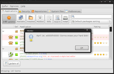
For those that know me, you probably have heard me talk about Sabayon and praise it for its flexibility, hardware support, good looks, humor (yes humor...see below for a nice April's Fools joke), and most importantly ease of use.
One of the nice things about Sabayon is that the kernel updating is quiet simple, given the complexities involved with the kernel. Below I outline a general procedure to help avoid any headaches one might have when updating their kernel.
1. Grab a list of drivers that will need to be updated:
2. Download/Install the kernel:
3. Install all packages listed in Step 1 (make sure to remove the version info otherwise you will just reinstall the current outdated package)
4. Verify that the kernel is selected:
5. If the new kernel is not selected with '*', set it with:
6. Also make sure opengl has the correct driver selected with:
7. Correct the opengl selection as needed with:
8. Make the new kernel the default option in grub (if so desired) by going to /boot/grub/menu.lst
9. Inside menu.lst change "default" to the the corresponding option.
10. It is also a good idea to run a dependency test and library test with:
And you should be good to go...NOT SO DIFFICULT IS IT?

One of the nice things about Sabayon is that the kernel updating is quiet simple, given the complexities involved with the kernel. Below I outline a general procedure to help avoid any headaches one might have when updating their kernel.
1. Grab a list of drivers that will need to be updated:
#equo query installed $(uname -r)
2. Download/Install the kernel:
#equo install sys-kernel/linux-sabayon
3. Install all packages listed in Step 1 (make sure to remove the version info otherwise you will just reinstall the current outdated package)
4. Verify that the kernel is selected:
#eselect kernel list
5. If the new kernel is not selected with '*', set it with:
#eselect kernel set [NUMBER]
6. Also make sure opengl has the correct driver selected with:
#eselect opengl list
7. Correct the opengl selection as needed with:
#eselect opengl set [NUMBER]
8. Make the new kernel the default option in grub (if so desired) by going to /boot/grub/menu.lst
9. Inside menu.lst change "default" to the the corresponding option.
10. It is also a good idea to run a dependency test and library test with:
#equo deptest
#equo libtest
And you should be good to go...NOT SO DIFFICULT IS IT?
Thursday, February 4, 2010
Setting up OpenCV in Eclipse on Windows
IF YOU ARE INSTALLING OPENCV VERSION 2.2 OR LATER PLEASE GO HERE INSTEAD: OpenCV 2.2 GUIDE.
First download and setup the basics:
- Get MinGW
- Download Eclipse C/C++ IDE
Note: I have a tutorial on these two steps already so just head over HERE for more info.
- Next download/install OpenCV 2.0 (OR download a more recent version)
- Now launch Eclipse and start a new project by going to:
- File->New->C++ Project (or File->New->C Project)
- Give your project a name in the "Project name" box
- Select the "Hello World" option under the "Project Type" section under the "Executable" folder. I recommend this over the "Empty Project" as it creates the c/c++ file for you instead of having to do it manually (it also creates a "src" folder and a "Debug" folder which helps keep things a little more organized)
- Make sure the "MinGW" Toolchain is selected in the "Toolchains" section
- Hit NEXT
- Fill in your Author and other file information, then hit NEXT
- In the next window select "Advanced settings...". This will bring you to the "Project Settings" which can always be accessed later by going to Project->Properties
- Under the "C/C++ Build" Section go to the "Settings" and select the "Tool Settings" Tab. Then select the "Includes" folder (on older versions of eclipse it is the "Directories" folder) in the GCC Compiler branch and add the opencv include directory to Include paths (-I): "C:\OpenCV2.0\include\opencv\". Of course, change C:\OpenCV2.0 to match the installed path that you used.
- Now, under the MinGW Linker select the "Libraries" folder and add the following to the Libraries (-l) section (note not all of these are necessarily needed for your project but these are all the libraries available in opencv):
- cv200
- cvaux200
- cxcore200
- cxts200
- highgui200
- ml200
In most cases you will only need cv200 and highgui200 to get started
ALSO NOTE: Versions 2.0 and later postfix the libraries names with a three digit number that corresponds to the version of OpenCV that you are linking to. Example: OpenCV2.1's highgui library must be linked using the name highgui210.
FINALLY, under the "Library search path (-L)" section add:
- "C:\OpenCV2.0\lib"
- Hit OK when done
- Hit Finish to create and start the Project
If you get an error, during compile time, pertaining to:
__exchange_and_add
Then visit this page and follow the instructions under:
Building on Windows using MinGW 3.4.5
Hope this helps!
Tuesday, January 26, 2010
Schematics for AngelBot - A Light Following Robot
So, I have been quite lazy as of late. This project has been sitting around at "near completion" for about 2 months. So I figure it is about time I post some of the schematics and parts used to make this Robot. As of right now this robot is completely wired up and inferaced to my FPGA; however, I am still "working on" getting the light steering circuit working properly in the code.
Here are the schematics:
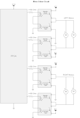
The "Motor Driver Circuit", does what it sounds like...it drives the motors; this circuit is used to interface the FPGA logic with the motors. Since the motors demand a significant amount of current to drive them (much more than the FPGA can provide), relays were used to create an interface between the logic and the motors which allows the motors to operate at full speed. Each side (left and right) are individually controlled via two SPDT relays. The relays used below are actually Dual SPST optical relays, but they can easily be wired up for SPDT operation. The NC (normally closed) state pushes 6V through the positive motor terminal which then goes to ground. The NO (normally open) state pushes 6V through the negative terminal which then goes to ground. An alternative H-Bridge Integrated Circuit could have been used to drive the motors; at the time of designing this circuit, I did not know of H-Bridges...but it turns out that is exactly what I designed! Catch Diodes may also be used to allow for additional protection and efficiency (but really are not needed in this implementation). Catch Diodes allow for a path for the electromagnetic field stored in an induction motor to deplete. These catch diodes are usually "schottky diodes" which are fast switching, low forward voltage diodes. These diodes are placed across each switching mechanism (i.e. transistor) in reverse bias configuration.
The "Collision Avoidance Circuit" is used to sense objects that are in close proximity and then steer away from the object. Infrared Proximity Sensors are used to acquire an analog voltage signal that is compared to a reference voltage that acts as the decision making device. These two IR sensors are mounted in front of the robot and are used to steer left or right. The third comparator in the circuit (in the middle), is used to make a decision as to which sensor detects a closer object. This third comparator will allow the robot to make an intelligent decision as to which way it should turn if a person or some non stationary object gets close to the robot.
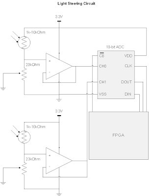
 The "Light Steering Circuit" is used to give the robot an objective other than avoiding collisions. When there are no objects being detected by the IR sensors, the Light Steering Circuit kicks in and guides the robot to locations containing high light intensity. In the future, I hope to addon to this robot and have a rechargable battery that is being powered by a photovoltaic cell. This circuit uses simple photocells to measure the light intensity. Again the robot uses stereoscopy to determine direction. A 10-bit ADC that communicates with the FPGA via the SPI (Serial Parallel Interface) protocol is used. The ADC wants a low impedance input, but doing so would cause problems with the photocell's voltage divider circuit being loaded down (effectively bypassing the 23K Ohm potentiometer), this means we need a buffer to create an intermediate stage that has a high input impedance and low output impedance.
The parts used are:
KNJN XYLO-LM FPGA board (used as the logic/brains of my robot). This is an EXPENSIVE piece of hardware, and I would NOT RECOMMEND getting this if you want to build a similar robot. There are much cheaper chips out there (i.e. PICS or even just a bunch of logic gates with a 555 timer chip) that can do the same thing this is doing. The only reason why I used an FPGA was because I already had the board and wanted to start another project with it.
http://www.knjn.com/ShopBoards_USB2.html
Mini Photocells (two of these are used in stereo to find the most intense lighting)
http://www.sparkfun.com/commerce/product_info.php?products_id=9088
10bit Analog-Digital Converter MCP3002 (used to acquire samples from the photocells)
http://dl.dropbox.com/u/767596/Resources/ROBO/21294C.pdf
I needed this 10-bit ADC versus a comparator because I wanted the robot to maintain going in a certain direction until there was a significant difference between the two photocells, otherwise the robot would constantly be turning left and right. This "difference parameter" is defined in my FPGA code. Eventually, I want to control this parameter through a Rotary encoder (which is basically a digital POT).
LM339 Quad Comparators (used as the decision making device for the obstacle avoidance system)
http://www.radioshack.com/product/index.jsp?productId=2062593
LM358 OpAmp (used to buffer the photocell signal, and make a high input impedance, low output impedance stage that goes into the 10bit ADC)
http://dl.dropbox.com/u/767596/Resources/ROBO/LM358.pdf
3.3 Voltage Regulator (used to power my FPGA board and some other components that want 3.3V instead of the 6V from my battery pack)
http://dl.dropbox.com/u/767596/Resources/ROBO/LD1117V33.pdf
Sharp IR Proximity Sensors (used to avoid obstacles by using two of them in stereo, and also used two additional sensors, one points down at the rear end and one pointing down at the front to avoid falling down a ledge)
http://dl.dropbox.com/u/767596/Resources/ROBO/GP2Y0A21YK.pdf
What's interesting about this sensor is the Voltage vs. Distance curve. Since the peak output voltage is at 6cm or so, and it drops off both as you increase and decrease in distance, I was able to split this curve into two sections. The 0-6cm range is used as the "drop-off detection" where I used the logic: if the distance is less than X cm away keep the motors in the default state, otherwise go into reverse. The 6-80cm range was used for the "object-avoidance circuit" that helped steer the robot when an object was in a defined range.
Wheel Encoders (used to track the wheel rotations, not actually implemented into my design yet)
http://www.sparkfun.com/commerce/product_info.php?products_id=9208
Micro Metal Gearmotor 100:1 (I use 4 of these motors, which enables the robot to have enough torque to go on carpet)
http://www.sparkfun.com/commerce/product_info.php?products_id=8910
SPDT Relay Switches (These are photo relay switches, so they don't even make the clicking noise. I use these to drive the motors from the 6V and GND supplies. I use 6V-->GND for the forward drive and the GND-->6V for the reverse drive)
http://dl.dropbox.com/u/767596/Resources/ROBO/ps7122a1c.pdf
Pictures, videos, and HDL code to come later!
Here are the schematics:
The "Motor Driver Circuit", does what it sounds like...it drives the motors; this circuit is used to interface the FPGA logic with the motors. Since the motors demand a significant amount of current to drive them (much more than the FPGA can provide), relays were used to create an interface between the logic and the motors which allows the motors to operate at full speed. Each side (left and right) are individually controlled via two SPDT relays. The relays used below are actually Dual SPST optical relays, but they can easily be wired up for SPDT operation. The NC (normally closed) state pushes 6V through the positive motor terminal which then goes to ground. The NO (normally open) state pushes 6V through the negative terminal which then goes to ground. An alternative H-Bridge Integrated Circuit could have been used to drive the motors; at the time of designing this circuit, I did not know of H-Bridges...but it turns out that is exactly what I designed! Catch Diodes may also be used to allow for additional protection and efficiency (but really are not needed in this implementation). Catch Diodes allow for a path for the electromagnetic field stored in an induction motor to deplete. These catch diodes are usually "schottky diodes" which are fast switching, low forward voltage diodes. These diodes are placed across each switching mechanism (i.e. transistor) in reverse bias configuration.

The "Collision Avoidance Circuit" is used to sense objects that are in close proximity and then steer away from the object. Infrared Proximity Sensors are used to acquire an analog voltage signal that is compared to a reference voltage that acts as the decision making device. These two IR sensors are mounted in front of the robot and are used to steer left or right. The third comparator in the circuit (in the middle), is used to make a decision as to which sensor detects a closer object. This third comparator will allow the robot to make an intelligent decision as to which way it should turn if a person or some non stationary object gets close to the robot.
 The "Light Steering Circuit" is used to give the robot an objective other than avoiding collisions. When there are no objects being detected by the IR sensors, the Light Steering Circuit kicks in and guides the robot to locations containing high light intensity. In the future, I hope to addon to this robot and have a rechargable battery that is being powered by a photovoltaic cell. This circuit uses simple photocells to measure the light intensity. Again the robot uses stereoscopy to determine direction. A 10-bit ADC that communicates with the FPGA via the SPI (Serial Parallel Interface) protocol is used. The ADC wants a low impedance input, but doing so would cause problems with the photocell's voltage divider circuit being loaded down (effectively bypassing the 23K Ohm potentiometer), this means we need a buffer to create an intermediate stage that has a high input impedance and low output impedance.
The parts used are:
KNJN XYLO-LM FPGA board (used as the logic/brains of my robot). This is an EXPENSIVE piece of hardware, and I would NOT RECOMMEND getting this if you want to build a similar robot. There are much cheaper chips out there (i.e. PICS or even just a bunch of logic gates with a 555 timer chip) that can do the same thing this is doing. The only reason why I used an FPGA was because I already had the board and wanted to start another project with it.
http://www.knjn.com/ShopBoards_USB2.html
Mini Photocells (two of these are used in stereo to find the most intense lighting)
http://www.sparkfun.com/commerce/product_info.php?products_id=9088
10bit Analog-Digital Converter MCP3002 (used to acquire samples from the photocells)
http://dl.dropbox.com/u/767596/Resources/ROBO/21294C.pdf
I needed this 10-bit ADC versus a comparator because I wanted the robot to maintain going in a certain direction until there was a significant difference between the two photocells, otherwise the robot would constantly be turning left and right. This "difference parameter" is defined in my FPGA code. Eventually, I want to control this parameter through a Rotary encoder (which is basically a digital POT).
LM339 Quad Comparators (used as the decision making device for the obstacle avoidance system)
http://www.radioshack.com/product/index.jsp?productId=2062593
LM358 OpAmp (used to buffer the photocell signal, and make a high input impedance, low output impedance stage that goes into the 10bit ADC)
http://dl.dropbox.com/u/767596/Resources/ROBO/LM358.pdf
3.3 Voltage Regulator (used to power my FPGA board and some other components that want 3.3V instead of the 6V from my battery pack)
http://dl.dropbox.com/u/767596/Resources/ROBO/LD1117V33.pdf
Sharp IR Proximity Sensors (used to avoid obstacles by using two of them in stereo, and also used two additional sensors, one points down at the rear end and one pointing down at the front to avoid falling down a ledge)
http://dl.dropbox.com/u/767596/Resources/ROBO/GP2Y0A21YK.pdf
What's interesting about this sensor is the Voltage vs. Distance curve. Since the peak output voltage is at 6cm or so, and it drops off both as you increase and decrease in distance, I was able to split this curve into two sections. The 0-6cm range is used as the "drop-off detection" where I used the logic: if the distance is less than X cm away keep the motors in the default state, otherwise go into reverse. The 6-80cm range was used for the "object-avoidance circuit" that helped steer the robot when an object was in a defined range.
Wheel Encoders (used to track the wheel rotations, not actually implemented into my design yet)
http://www.sparkfun.com/commerce/product_info.php?products_id=9208
Micro Metal Gearmotor 100:1 (I use 4 of these motors, which enables the robot to have enough torque to go on carpet)
http://www.sparkfun.com/commerce/product_info.php?products_id=8910
SPDT Relay Switches (These are photo relay switches, so they don't even make the clicking noise. I use these to drive the motors from the 6V and GND supplies. I use 6V-->GND for the forward drive and the GND-->6V for the reverse drive)
http://dl.dropbox.com/u/767596/Resources/ROBO/ps7122a1c.pdf
Pictures, videos, and HDL code to come later!
Subscribe to:
Posts (Atom)