I stumbled across an interesting post that led me to this site:
pshdl.org
It seems that there is an effort to create a new language that replaces/overlays traditional HDL such as Verilog and VHDL. The thought is that these languages originate pre-FPGA and have a lot of non-synthesizable concepts built into them. PSHDL may become a language that simplifies the general learning curve and process of realizing synthesizable designs. If you go to the root page of the link sited above, it will bring you to a webtool for generating equivalent, presumably, synthesizable HDL code.
Wednesday, January 22, 2014

Sunday, November 24, 2013
PWM VHDL Module
Here is yet another PWM (Pulse Width Modulation) module! What distinguishes this module from most other PWM modules is that it's parameterized. When dealing with LEDs this becomes a very useful feature since each type of LED responds differently (in terms of light) when presented with a PWM signal. This module will allow you to adjust the clock prescaler and the number of quantas. What does this mean you ask? Let me explain with the help of a simple picture...

Basically the PWM signal is produced via a multi-process module. The first process is a "prescaling process". This process takes the input clock and divides it down by the amount you specify. This process is not critical towards its operation and could be removed if you want to minimize your logic.
The next process is the "Accumulate process". This process is responsible for determining when to switch the PWM outputs logic state. Basically it takes the prescaler's divided clock and accumulates/increments a counter on each cycle. One time "quanta" is equivalent to one cycle of the PWM divided clock.
The final process is the "modulate" process. This is the key process to generating the PWM signal. It determines when to switch the PWM output signal based on the PWM accumulator and the PWM input signal. The accumulator continually counts up towards the maximum quanta value and then rolls over to 0 where the process continues to count. The PWM input determines when to bring the PWM output low. A larger PWM input means the PWM output will remain HI for a longer period of time which produces a brighter output on the LED (or dimmer depending on how the LED is connected). In order to maintain a constant level of illumination it is important to ensure that the refresh rate of the PWM cycle is above the human eye's flicker fusion rate. This is generally understood to be around 16Hz but you should target 60Hz or higher. The general criteria for these configurable parameters should satisfy the following equation:
Here is a demo of this module running on a Terasic DE0-NANO.
Download: PWM.vhd

The next process is the "Accumulate process". This process is responsible for determining when to switch the PWM outputs logic state. Basically it takes the prescaler's divided clock and accumulates/increments a counter on each cycle. One time "quanta" is equivalent to one cycle of the PWM divided clock.
The final process is the "modulate" process. This is the key process to generating the PWM signal. It determines when to switch the PWM output signal based on the PWM accumulator and the PWM input signal. The accumulator continually counts up towards the maximum quanta value and then rolls over to 0 where the process continues to count. The PWM input determines when to bring the PWM output low. A larger PWM input means the PWM output will remain HI for a longer period of time which produces a brighter output on the LED (or dimmer depending on how the LED is connected). In order to maintain a constant level of illumination it is important to ensure that the refresh rate of the PWM cycle is above the human eye's flicker fusion rate. This is generally understood to be around 16Hz but you should target 60Hz or higher. The general criteria for these configurable parameters should satisfy the following equation:
60<=(f_CLK/prescaler)/quantas
For instance, a 100MHz clock prescaled by 3125 with 128 time quantas yields a refresh rate of 250Hz which is well above the minimum and should be visually flicker-free.
Here is a demo of this module running on a Terasic DE0-NANO.
Download: PWM.vhd
Friday, November 22, 2013
Gtk+ Si47xx Radio
Well...it's been a while since I have posted anything. So here is a little teaser of something that I have been casually working on. This is another radio project, this time on a RaspberryPi (RPi) using the same Si4735 chip as my other radio project and using a revamped object oriented design on the Si47xx library. Currently, this Gtk+ GUI you see below runs directly off of the RPi and I use X11 Forwarding to bring the GUI to my local PC, effectively giving me remote control over the radio. But as you can see from the GUI's "Network" menu item. I am in the process of bringing this GUI to the local PC and then remotely connect to a radio server that runs on the RPi. This will be (most likely) a TCP socket where the server will push the RDS/RBDS data to the client and the client will populate the corresponding GUI elements with the received data.

Saturday, February 25, 2012
BatchPCB

Saturday, February 4, 2012
Dropbox Special Forum Build
For those that haven't heard, Dropbox is a great utility for synchronizing data between multiple computers and portable devices while giving you basic version control, file hosting, and collaborative group folders capabilities. It's my cloud storage of choice for it's ease of use, cross-platform capabilities, and streamlined interface that blends right into your OS.

Anyways I came across an article that pointed me to this forum post: Dropbox forum
Essentially, it says that if you are willing to partake in an experiment you can get up to 5GB of storage free as opposed to the standard 2GB free.

Anyways I came across an article that pointed me to this forum post: Dropbox forum
Essentially, it says that if you are willing to partake in an experiment you can get up to 5GB of storage free as opposed to the standard 2GB free.
Friday, January 27, 2012
FPGA to 74HC595 Shift Register Module in Verilog
I have had this 74HC595 IC sitting around for quite some time. And earlier this week I decided it was time for me to actually start using it...or at least start learning how I could use it. This chip is a Serial-In Parallel-Out 8-bit shift register that can be used in a variety of ways and it can be cascaded with more of these ICs to create a larger shift register if needed. My plan is to use this newly developed module to act as a low pin count interface between the FPGA and my 16x2 Character LCD module. This will allow me to utilize 4-wires to control the 8-bit parallel interface on the LCD (not including the LCD control lines). This reduced the FPGA pin utilization from 11 pins down to 7 pins...not to shabby. Anyways for those that are interested, the code is linked below. Please note: this module is very much application specific and that it does not enable all practical uses of the 74HC595 IC. For instance, the SRCLR signal is not used and is permanently tied to VCC so that it never clears the register; this of course, may not suit your needs, however the code is heavily commented and adaptation of the code should be fairly simple.
Simulation:
The functional operation of the module can be seen in this timing diagram simulation:

The yellow markers are showing the beginning and end of one complete 8-bit shift operation. This simulation is using a 50ns clock period which is slightly slower than the 24MHz clock that my actual FPGA is using. This simulation shows that it takes about 89 clocks to process a request. 89 clocks at 24MHz is about 3.7us.
Signal Descriptions:
Simulation:
The functional operation of the module can be seen in this timing diagram simulation:

Signal Descriptions:
- RDY: A bit that indicates that the FPGA_2_ShiftReg is idle and is ready to process a request
- RCLK: A signal sent to the shift register which instructs the output registers to read from the shift register taps
- SRCLK: A signal sent to the shift register which instructs the 8-bit shift register to shift the register bits and read from the serial input and push it into the LSB.
- OE: A signal sent to the shift register which sets the output in either Hi-Z (output disabled) or Lo-Z (output enabled). This is an active low signal.
- SER_OUT: The Serial signal sent to the shift register.
- CLK: The FPGA's local oscillator which drives the rest of the logic.
- BYTE_IN: An 8-bit value that is fed into the FPGA_2_ShiftReg module
- PB: A signal created for simulation purposes to instruct the module to read the 8-bit value from BYTE_IN. Every time this pushbutton is pressed the FPGA_2_ShiftReg module is activated and instructed to read the BYTE_IN. Also the driving module (the module that instantiates and uses the FPGA_2_ShiftReg module) increments the BYTE_IN value by one.
DOWNLOAD: FPGA_2_ShiftReg GitHub Repo
Wednesday, December 28, 2011
An implementation of a basic character LCD controller in Verilog
For a while now, I have been wanting to post my code that I developed during my GPS project using a FPGA board. Creating the LCD controller module was the meat of the project and I know many people are interested in how one might approach such a project. I have plans on providing a full-fledged tutorial on how I designed this module, but it is still in the works. In the meantime, I will provide you with the Verilog code which is fairly well commented and with a little cross correlation with the data sheet for the ST7066 the code should be for the most part, self-explanatory. Eventually this post will be edited with a more formal discussion of this code but for now we will have to make due with just the code.
Here is a screenshot of a simulation of what this module does after the initialization phase and you write the ascii value of "C" (0x43) as a data operation. The markers indicate the start and end of the module's execution of this operation.

Here is a screenshot of a simulation of what this module does after the initialization phase and you write the ascii value of "C" (0x43) as a data operation. The markers indicate the start and end of the module's execution of this operation.

DOWNLOAD: FPGA_2_LCD.v
Saturday, September 17, 2011
C/C++ Callback functions
So one of my projects I have been working on with the Arduino UNO required the use of an interrupt. For those not familiar with an interrupt it essentially is a mechanism that allows the code to branch off of its normal routine and execute a separate set of code. This is great for devices such as a rotary encoder that act as a volume knob or some other control mechanism since it will immediately interrupt the current code and execute the code associated with the interrupt. I was developing a nice set of library functions for a rotary encoder class library and thought that it would be nice to have a command like:
Rotary ROT;
ROT.begin(EncA,EncB,PB,CallbackFcn);
The purpose of this method would be to configure the rotary encoder inputs (EncA, EncB) to their proper modes and then create a callbackfcn that would execute every time one of these changed. The arduino library has a function that allows you to attach an interrupt to a pin and associate that interrupt pin with a callback function. But I wanted to allow the user to utilize my Rotary Class without having to specify the callback function within the library itself. This required me to learn how to create a "function pointer".
To create a function pointer is simple. Suppose we have a local function called CallbackFcn that takes in no input arguments. We can create a method that takes a function pointer as an input argument such as:
void Rotary::begin(int EncA, int EncB, int PB, void (*CALLBACK)(void)){
//Stuff goes here
}
That is all there is to it.
Rotary ROT;
ROT.begin(EncA,EncB,PB,CallbackFcn);
The purpose of this method would be to configure the rotary encoder inputs (EncA, EncB) to their proper modes and then create a callbackfcn that would execute every time one of these changed. The arduino library has a function that allows you to attach an interrupt to a pin and associate that interrupt pin with a callback function. But I wanted to allow the user to utilize my Rotary Class without having to specify the callback function within the library itself. This required me to learn how to create a "function pointer".
To create a function pointer is simple. Suppose we have a local function called CallbackFcn that takes in no input arguments. We can create a method that takes a function pointer as an input argument such as:
void Rotary::begin(int EncA, int EncB, int PB, void (*CALLBACK)(void)){
//Stuff goes here
}
That is all there is to it.
Tuesday, August 2, 2011
Si4735 AM/FM/SW/LW Radio Project
[KEY DOWNLOADS]
[UPDATE #9]
Summary of changes specific to Si4735 library:
[UPDATE #8] I have updated the library once again. Here is an incomplete list of changes:
[UPDATE #7] My advanced radio project file is now included under the examples section of the Si4735 library repository. I also made a small update to the library to adjust the deemphasis to the proper levels depending on the region/locale you have specified when calling the setLocale method.
[UPDATE #6] I have finally made my radio project public! For now you can download my pde file and the accompanying libraries (with exception to the Si4735 library which you can just grab the normal way) in my GitHub downloads section. I am still trying to learn how to add files to an existing fork'ed repository, but once I figure that out, I will be adding these files to the "examples" folder in the Si4735 repo. If you have any questions pertaining to this project please let me know. I tried my best to comment most of the code without being overly verbose so some stuff is bound to cause a few people to scratch their heads.
Hopefully this example will provide users with enough insight on how "one" might use the different features that exist in the library.
I still have plans to add USE_FLAGS (as described in the previous update) but I have been busy with other things at the moment.
[UPDATE #5] The Si4735 library has been updated again, here are some of the changes:
Also, one thing I forgot to show off last time was my scanFreq Labview program that communicates with the Arduino and runs through a series of tuneFrequency() and getRSQ() calls. The program takes the SNR information acquired from the chip and plots it versus frequency. This is makes for a very basic spectrum analyzer over the FM frequency band. I would not rely on the metrics too much but they certainly give you a general idea of what to expect for sound quality when tuning to a particular frequency.

My next update will be a small one which is to enable the "date" field in the Today structure. This date field will contain the current year, month, and day.
Also as a side note, I will be providing access to my Arduino Sketch in the near future. This will probably be at the same time I perform the above mentioned update to the library
[UPDATE #1] Below is a video update to my project. I have now added RDS/RBDS support to my project as well as a LabView interface for controlling the device through the USB/COM port.
ORIGINAL POST

- Si4735 library
- Labview Frequency Scan Example (screenshot)
- Labview Radio Controller (dependancies: select_com.vi) (screenshot)
[UPDATE #9]
Summary of changes specific to Si4735 library:
- Added support for USE flags. These flags make it quick and easy to strip down the Si4735 library features and will ultimately help you save memory space at the cost of features.
- Added setProperty and getProperty methods. This will make it very easy for individuals to easily customize the functionality and properties of the Si4735 chip. Consult the Si4735 programmers manual for the register addresses, properties, and acceptable values.
- Added seekThresholds method to allow the user a quick and easy way to adjust the seek SNR and RSSI thresholds.
- Added a new field to the Station struct that indicates when the radioText has changed (or is being changed). The radio text is usually left unchanged during a song so this could be used to detect that a new song is playing and you could create an event that triggers off of this flag. This boolean field should only stay high for one readRDS call.
- 'visible' method added to SerLCD.
- Added a reset baud function to the setBaud method in SerLCD. Issuing setBaud(0) while the splash screen is being displayed will set SerLCD to 9600 baud.
- Fixed typo in serCommand method in SerLCD library
- increased stability of sketch by disabling interrupts during callback execution. This should help minimize the frequency of system freeze-up (I don't think it eliminates it completely though).
- SerLCD is automatically reconfigured to it's maximum supported baud rate of 38400baud. Note there is a known bug where after a cold start-up (arduino completely discharged) that the sketch will not complete the setup process (it will stop at "Loading-Up"). A simple reset will allow it to successfully load.
- Increased the seek process' sensitivity. It will now detect more "good" quality stations by default.
 |
| Si4735 Shield with custom made Logic Level Converter PCB attached |
[UPDATE #8] I have updated the library once again. Here is an incomplete list of changes:
- Updated the code to be compatible with the Arduino IDE v1.0
- Added SerLCD.cpp to the repo. SerLCD.h is now an actual class library.
- Added Rotary_one class library to the repo. This is a single interrupt rotary encoder library. It is not prefect by any means but it is a step in the right direction. Freeing up pin 2 means I can start working on utilizing the Si4735 interrupt capabilities. The original rotary encoder library is left untouched and the two are interchangeable. By default the original is still being used, but in the future, I plan on fine tuning this library so that it is as responsive as the old one, but I have no plans on when that may be.
- Made minor adjustments to my Si4735_Advanced_Radio project to address a few minor bugs. Audio quality will be slightly cleaner on stations that don't have RDS/RBDS program services. I was constantly writing on the UART line in these circumstances, which created unnecessary noise.
[UPDATE #7] My advanced radio project file is now included under the examples section of the Si4735 library repository. I also made a small update to the library to adjust the deemphasis to the proper levels depending on the region/locale you have specified when calling the setLocale method.
[UPDATE #6] I have finally made my radio project public! For now you can download my pde file and the accompanying libraries (with exception to the Si4735 library which you can just grab the normal way) in my GitHub downloads section. I am still trying to learn how to add files to an existing fork'ed repository, but once I figure that out, I will be adding these files to the "examples" folder in the Si4735 repo. If you have any questions pertaining to this project please let me know. I tried my best to comment most of the code without being overly verbose so some stuff is bound to cause a few people to scratch their heads.
Hopefully this example will provide users with enough insight on how "one" might use the different features that exist in the library.
I still have plans to add USE_FLAGS (as described in the previous update) but I have been busy with other things at the moment.
[UPDATE #5] The Si4735 library has been updated again, here are some of the changes:
- Added the retrieval of the UTC month, day, and year(2-digit). Note the hour and minute that are provided in the "Today" structure are local values and not the UTC values. This may change in the future.
- Fixed the hour and minute computation. These were being incorrectly computed due to a couple mathematical errors.
- Compacted the Program Type lookup tables into one large LUT. This reduces redundancy and ultimately saves space.
- Added a private function that helps filter out non-printable characters from strings that are meant to be printed.
[UPDATE #4] This is a quick update to show my audio amplifier circuit at work. I decided against throwing in a preamp into the mix and just went with an LM386N-1. The audio quality is very nice considering the parts being used. There is a little bit of audio clipping occurring when I set the audio at 100%, which I imagine I can eliminate by swapping out my 9V regulated DC adapter with a 12V regulated DC adapter. The speaker that I used was one of my car's old stock speakers. I plan to make another identical circuit so that I can get stereo output, but before I get into that, I will need to start thinking of an enclosure to start housing this stuff.
Also, one thing I forgot to show off last time was my scanFreq Labview program that communicates with the Arduino and runs through a series of tuneFrequency() and getRSQ() calls. The program takes the SNR information acquired from the chip and plots it versus frequency. This is makes for a very basic spectrum analyzer over the FM frequency band. I would not rely on the metrics too much but they certainly give you a general idea of what to expect for sound quality when tuning to a particular frequency.

For those interested in this you can download it here: download (note: make sure to change the REFRESH/HOLD button to REFRESH when you want to reacquire the data. HOLD will simply maintain the current data)
The code essentially expects comma separated values (see the code below for the exact form of the output). The function below will interface with the Labview code perfectly (assuming you define your Si4735 class as "radio" and that you are using my latest version of the library).
[UPDATE #3] I got around to updating the Si4735 library. BE WARNED, this update WILL BREAK YOUR CODE...however, in my opinion this update is a necessary step forward and future updates will be less painful for both the users and the developers. Here is an incomplete list of changes and additions:
- Created a Metrics structure, making the getRSQ method a lot simpler to interface
- Created a Station structure, making the getRDS method a lot simpler to interface
- Created a getTime method and a Today structure which acquires the station's local time (eventually this will also include the date, but currently it only contains the 24-hour time). Note this data field is rarely transmitted (most stations send time/date information about 1 time a minute)
- Removed unused return values (mainly to clean up the code)
- Added the ability to set (and get) the "locale" (setLocale) to either NA (North American) or EU (European). This effectively sets the look-up table to use for the Program Type.
- Added setMode and getMode methods. The setMode method calls the "end" method which effectively powers down the Si4735 and the changes then mode. The user is responsible for calling the "begin" method again.
- Added the interpretation/conversion of the PI field to a Callsign. It seems that not many stations (atleast where I live) use this field. The callsign is the 4 (or 3) letter identification assigned/used by radio station, such as WHEB or KHNN. Note: 3 letter stations are currently not supported in this code but it is on my list of TODOs.
My next update will be a small one which is to enable the "date" field in the Today structure. This date field will contain the current year, month, and day.
Also as a side note, I will be providing access to my Arduino Sketch in the near future. This will probably be at the same time I perform the above mentioned update to the library
[UPDATE #2] Here is another update showing performance improvements and added features such as showing the Program Type field (PTY). I have also added a getRSQ method to the library that can be used to get the "Received Signal Quality" of the tuned station. This method provides the following metrics:
STBLEND - Percent Stereo Blend [0 = Mono, 100 = Stereo]For those interested in accessing the library that my code is running off of (for the most part...there are some minor differences), you can head over to: github Si4735. This is a fork of Trunet's repository with some additions, tweaks, and minor bug fixes.
RSSI - Receive Signal Strength Indicator [0 - 127 dBuV]
SNR - Signal to Noise Ratio [0 - 127 dB]
MULT - Multipath [0 = No multipath, 100 = Full multipath]
FREQOFF - Signed Frequency offset
[UPDATE #1] Below is a video update to my project. I have now added RDS/RBDS support to my project as well as a LabView interface for controlling the device through the USB/COM port.
ORIGINAL POST
I recently acquired an Arduino board and I have found that it is at least 100 times easier to develop/design projects than an FPGA. Don't get me wrong I still prefer FPGA (I feel like I am more in control of what I do), but programming hardware from a C/C++ level is so much easier in comparison to HDL programming. This fact, coupled with the fact that the Arduino is an open source, driven community, hardware/software platfrom makes for a very user friendly environment.
Anyways, I decided to jump into the realm of Radio by using Sparkfun's Si4735 Shield. The Si4735 is a pretty impressive chip that has a lot of functionality in a small form factor. Check out the video and see the basic block diagram of this project. When I get around to it, I will provide more details here.

Things that need improving:
You might have noticed in the video that the rotary encoder had an issue when I was attempting to change the frequency in "stepped" mode. This is a bug that currently only exists while in this mode. I am not sure if the underlying cause is my rotary encoder's debouncing algorithm or if it is some weird timing issue.This was fixed via modification to my rotary encoder callback procedureThe rotary encoder's debouncing algorithm also needs improvement, while the performance is reasonable, it is far from perfect and needs some fine tuning.Updating my code and cleaning up my wiring helped a lot.- There appears to be an issue with using a power source connected to the Arduino's external power jack (instead of using the USB's supplied power). The SPI interface becomes a little unreliable.
Overall though this project, when powered from the USB port, is very reliable and user friendly. I have a few neat ideas for adding onto this project that I will share at a later time. The performance of the Radio shield is very good considering that the FM signal that I was receiving were coming from the line out (that is wired to my amplifier and speakers), and the audio quality was exceptional.
Sunday, June 26, 2011
MTK NMEA checksum calculation
The MTK NMEA checksum can be calculated by using the following procedure:
The NMEA Checksum is calculated on a character by character basis using an XOR operator. Each character is fed into an XOR with the current checksum value. The checksum is initialized to all zeros. The characters that exist between the "$" and "*" are the only characters to be used in the calculation. These values are in ASCII, thus each character is represented as an 8-bit value. The resulting checksum is an 8-bit HEX value which is represented as 2 ASCII characters. Below is an example of this procedure:
$PMTK000*32
0000 0000 <==Checksum
0101 0000 <==P
0101 0000 <==Checksum
0100 1101 <==M
0001 1101 <==Checksum
0101 0100 <==T
0100 1001 <==Checksum
0100 1011 <==K
0000 0010 <==Checksum
0011 0000 <==0
0011 0010 <==Checksum
0011 0000 <==0
0000 0010 <==Checksum
0011 0000 <==0
0011 0010 <==Checksum
This results in a checksum of 32 which matches what was shown above.
And for those folks that use MATLAB, HERE is a very basic program that I wrote up that does this for you.
Enjoy!
The NMEA Checksum is calculated on a character by character basis using an XOR operator. Each character is fed into an XOR with the current checksum value. The checksum is initialized to all zeros. The characters that exist between the "$" and "*" are the only characters to be used in the calculation. These values are in ASCII, thus each character is represented as an 8-bit value. The resulting checksum is an 8-bit HEX value which is represented as 2 ASCII characters. Below is an example of this procedure:
$PMTK000*32
0000 0000 <==Checksum
0101 0000 <==P
0101 0000 <==Checksum
0100 1101 <==M
0001 1101 <==Checksum
0101 0100 <==T
0100 1001 <==Checksum
0100 1011 <==K
0000 0010 <==Checksum
0011 0000 <==0
0011 0010 <==Checksum
0011 0000 <==0
0000 0010 <==Checksum
0011 0000 <==0
0011 0010 <==Checksum
This results in a checksum of 32 which matches what was shown above.
And for those folks that use MATLAB, HERE is a very basic program that I wrote up that does this for you.
Enjoy!
Saturday, June 25, 2011
GPS to 16x2 Character LCD Using an FPGA
Note: The GPS coordinates shown will not lead you to me. The GPS module at the time of recording this, was not locked onto my coordinates...so don't try hunting me down..else you will find yourself in the Atlantic =P
Below is a basic block diagram that helps to illustrate what the FPGA does in the system. The FPGA has 3 modules: A Serial Module, a Parser Module, and an LCD Controller Module. The serial module is only responsible for acquiring the serial data at the specified baud rate. Over sampling is used in the FPGA to help minimize bit errors. The serial module passes the raw data to the parser module. At this point in time the raw data is the NMEA messages (with the overhead information removed, i.e. stopbit/startbit). The parser module waits for the occurrence of a '$' which indicates the start of an MTK/NMEA message. Once the '$' is received, the parser extracts the message type and checks for a "GGA" message. If the current message is a GGA message, then we extract the Latitude and Longitude based on the standard format of the GGA message. This is currently being done by counting the characters; however, counting the comma delimiters work just as well. The parser module passes the latitude and longitude data to the LCD module as it is received on the serial line. The LCD controller module handles the initialization process required to set the LCD module into an operative mode, and it handles all the timing and writing data to the display.

This is an on-going project and I plan to add many more features to it. Below are some changes that I plan on making in the future.
For those interested in knowing more about this project, or want more information about certain aspects of the HDL code that I wrote, please don't hesitate to post a comment.
For those interested in the LCD controller module's code, go here: LCD Controller.
Or to download all of the related HDL files, go here: GPS2LCD_Files.zip
My project was featured on Sparkfun's Main Page! Pretty cool and I got some good constructive criticism.
Future Improvements/Additions:
- Write the serial stream from the serial module to a Block Memory or RAM
- Read the data in a Block Memory or RAM and feed the data into the Parser Module.
- Perform mathematical operations on the acquired data, such as computing the displacement from the current location to the last saved location.
For those interested in the LCD controller module's code, go here: LCD Controller.
Or to download all of the related HDL files, go here: GPS2LCD_Files.zip
My project was featured on Sparkfun's Main Page! Pretty cool and I got some good constructive criticism.
Thursday, May 19, 2011
Using an MCP3002 ADC for Interfacing an FPGA with a Photocell
The MCP3002 ADC Chip is a very handy device. You can interface with it via a very simple SPI (Serial Peripheral Interface) protocol. The Verilog module that I designed to interface with this chip works beautifully.
The module I created uses both channels of the MCP3002 in an "interlaced" single-ended mode. The module is strictly configured to work with a local oscillator of 24MHz, but minor adjustments to the process that converts the local clock to a 1.2MHz clock is all that needs to be modified. The 1.2MHz clock is the maximum frequency that the IC can operate at while powered at 2.7V as specified in the datasheet (pg3) under the "Timing Parameters". In my case my FPGA uses 3.3V logic so Fclk(max) should reside somewhere between this and 3.2MHz. If we assume a linear relationship between voltage and operating frequency, then the maximum expected operating frequency at 3.3V would be ~1.688MHz, thus operating at 1.2MHz "should" be a safe level of operation while pushing the IC to work at its maximum.
As far as the code goes, it is really self explanatory. I would recommend anyone that is attempting to use this code to have a copy of the datasheet on hand so that you can see the relationship from my code and the datasheet's timing diagram. Figure 5-1 was specifically used to design this Verilog Module.
On a hardware interfacing note, be sure to pay attention to Figure 4-2 in the datasheet, this clearly states that the ADC's CH0 and CH1 input signals NEED to be buffered (i.e. use an opamp in a buffer configuration or similar). If you skip this, your maximum operating frequency will be lower that the one defined in the datasheet.
The code that I provide here is free to use however you would like, but I would appreciate it if you give me credit for my work. Also constructive criticism is welcome, if you see something that could be done better another way, let me know.
Download: MCP3002 ADC Module
The module I created uses both channels of the MCP3002 in an "interlaced" single-ended mode. The module is strictly configured to work with a local oscillator of 24MHz, but minor adjustments to the process that converts the local clock to a 1.2MHz clock is all that needs to be modified. The 1.2MHz clock is the maximum frequency that the IC can operate at while powered at 2.7V as specified in the datasheet (pg3) under the "Timing Parameters". In my case my FPGA uses 3.3V logic so Fclk(max) should reside somewhere between this and 3.2MHz. If we assume a linear relationship between voltage and operating frequency, then the maximum expected operating frequency at 3.3V would be ~1.688MHz, thus operating at 1.2MHz "should" be a safe level of operation while pushing the IC to work at its maximum.
As far as the code goes, it is really self explanatory. I would recommend anyone that is attempting to use this code to have a copy of the datasheet on hand so that you can see the relationship from my code and the datasheet's timing diagram. Figure 5-1 was specifically used to design this Verilog Module.
On a hardware interfacing note, be sure to pay attention to Figure 4-2 in the datasheet, this clearly states that the ADC's CH0 and CH1 input signals NEED to be buffered (i.e. use an opamp in a buffer configuration or similar). If you skip this, your maximum operating frequency will be lower that the one defined in the datasheet.
The code that I provide here is free to use however you would like, but I would appreciate it if you give me credit for my work. Also constructive criticism is welcome, if you see something that could be done better another way, let me know.
Monday, May 2, 2011
Setting up OpenCV in Eclipse on Windows (OpenCV2.2)
The latest release of OpenCV (version 2.2) has undergone dramatic changes to the library. Because of these changes, my older guide is now outdated. For OpenCV version 2.2, please use this guide.
Then visit this page and follow the instructions under:
Building on Windows using MinGW 3.4.5
Hope this helps!
First download and setup the basics:
- Get MinGW
- Download Eclipse C/C++ IDE
Note: I have a tutorial on these two steps already so just head over HERE for more info.
- Next download/install OpenCV 2.2
- Now launch Eclipse and start a new project by going to:
- File->New->C++ Project (or File->New->C Project)
- Give your project a name in the "Project name" box
- Select the "Hello World" option under the "Project Type" section under the"Executable" folder. I recommend this over the "Empty Project" as it creates the c/c++ file for you instead of having to do it manually (it also creates a "src" folder and a"Debug" folder which helps keep things a little more organized)
- Make sure the "MinGW" Toolchain is selected in the "Toolchains" section
- Hit NEXT
- Fill in your Author and other file information, then hit NEXT
- In the next window select "Advanced settings...". This will bring you to the "Project Settings" which can always be accessed later by going to Project->Properties
- Under the "C/C++ Build" Section go to the "Settings" and select the "Tool Settings"Tab. Then select the "Includes" folder (on older versions of eclipse it is the "Directories" folder) in the GCC Compiler branch and add the opencv include directory to Include paths (-I): "C:\OpenCV2.2\include\". Of course, change C:\OpenCV2.2 to match the installed path that you used.
- Now, under the MinGW Linker select the "Libraries" folder and add the following to the Libraries (-l) section (note not all of these are necessarily needed for your project but these are all the libraries available in opencv version 2.2):
- opencv_calib3d220
- opencv_contrib220
- opencv_core220
- opencv_features2d220
- opencv_ffmpeg220
- opencv_flann220
- opencv_gpu220
- opencv_highgui220
- opencv_imgproc220
- opencv_legacy220
- opencv_ml220
- opencv_objdetect220
- opencv_ts220
- opencv_video220
In most cases you will only need opencv_core220 and opencv_highgui220 to get started
NOTE: Versions 2.2 and later postfix the libraries names with a three digit number that corresponds to the version of OpenCV that you are linking to.
FINALLY, under the "Library search path (-L)" section add:
- "C:\OpenCV2.2\lib"
- Hit OK when done
- Hit Finish to create and start the Project
NOTE: The way this guide was written will require you to use a relative path to specify the header files you wish to include. OpenCV breaks up the library into two sections, "legacy libraries" and "new libraries".
If you wish to specify one of the new opencv libraries use the following format:
#include "opencv2\[subfolder]\[library.hpp]"
ADDITIONALLY, if you wish to include all of the primary opencv2 header files in a project you can use:
#include "opencv2\opencv.hpp"
Note: opencv.hpp does not include every library in OpenCV2.2. It may be helpful for you to view the "opencv.hpp" library (located by default in: C:\OpenCV2.2\include\opencv2\opencv.hpp) to see what is included and how you can reference the new libraries in your code. To see the complete list of libraries available, go to "C:\OpenCV2.2\include\" and browse around the directory.
Legacy libraries can be defined by: #include "opencv\[library.hpp]"
If you get an error, during compile time, pertaining to:
__exchange_and_addThen visit this page and follow the instructions under:
Building on Windows using MinGW 3.4.5
Hope this helps!
Tuesday, February 15, 2011
UWB Channel Model with People Shadowing Process

Here is the abstract:
This report covers the topic described by, A Packet-Level Model for UWB Channel with People Shadowing Process Based on Angular Spectrum Analysis, written by Ruonan Zhang and Lin Cai. The presented closed-form solutions to Angular Power Spectrum Analysis, the People Shadowing Process, and the Finite State Markov Chain Model will be discussed and related to the general material learned during a graduate-level Wireless Communications course. Simulation results will be compared and analyzed. This paper will confirm that the results present by Ruonan Zhang and Lin Cai are valid methods to simulate the people shadowing process for a packet-level model for UWB channels.
Friday, January 7, 2011
Dithering Methods and Applications
In this paper, the topic of digital halftones, or dithering, is discussed. In particular, the methods of implementation are discussed for the three classical categories which are random, ordered, and error diffusion dithering. A good understanding of dithering is necessary prior to understanding how and when dithering is necessary or beneficial to the designer. This paper includes discussions of specific types of dithering including one of the most popular techniques called Floyd-Steinberg and also includes actual implementations in MATLAB [See Appendix]. Several applications will be discussed that encompass not only image processing but audio signal processing, and optics.


Monday, October 4, 2010
Electromagnetic Wave Theory
So I am taking a follow up class (graduate-level) on the undergraduate-level Electromagnetic Fields and Waves course. It has been quite some time since I have looked at material like this in considerable depth and I have found that I need to re-introduce myself to many concepts.
Anyways, during my search I came across this handy resource. It has helped me understand several concepts I was having difficulties understanding, and with the examples they give, I can also re-learn good methods of approaching the problems at hand.
Anyways, during my search I came across this handy resource. It has helped me understand several concepts I was having difficulties understanding, and with the examples they give, I can also re-learn good methods of approaching the problems at hand.
Wednesday, June 9, 2010
Creating/Adding an NFS Share
A couple days ago I had to create an NFS share at work. I never had to create one before but I found it to be quite painless. Here's how I did it in Sabayon Linux:
1. Start the nfs daemon if it is not already launched:
2. Edit the /etc/exports file (create it if needed) to include the share you wish to allow access to using the following syntax:
Example:
3. Update the exports by running:
Note: you may see some output warnings, but it will most likely still work.
4. You should now be able to mount the nfs share on the client
1. Start the nfs daemon if it is not already launched:
#/etc/init.d/nfs start
2. Edit the /etc/exports file (create it if needed) to include the share you wish to allow access to using the following syntax:
[full_path_to_share] [client_ip] ([privalages])
Example:
/home/aether/share 192.168.64.100 (rw)
3. Update the exports by running:
#exportfs -rv
Note: you may see some output warnings, but it will most likely still work.
4. You should now be able to mount the nfs share on the client
Tuesday, May 25, 2010
Bootloader Emulation
Modifying settings on a boot loader can be somewhat annoying; especially if you are inexperienced at it since you are prone to breaking the bootloader. When a bootloader is broken, often times you are forced to resort to throwing in a LiveCD/DVD and chrooting your filesystem and re-installing a fresh untampered bootloader. This is a time consuming and very annoying process. So...why not run an emulator of your current configuration so that in the event that the bootloader is broken, you know about it before you have to reboot. This allows the user to repair the bootloader in his filesystem rather than chrooting and all that mess that follows.
How do you emulate a bootloader you ask?
Simply download and install "qemu". For sabayon users just:
Then when the package is properly installed, run this:
This assumes the bootloader is on the MBR. Adjust the command accordingly.
Not too shabby!
How do you emulate a bootloader you ask?
Simply download and install "qemu". For sabayon users just:
#equo install qemu
Then when the package is properly installed, run this:
#sync ; echo 3 > /proc/sys/vm/drop_caches ; qemu -hda /dev/sda
This assumes the bootloader is on the MBR. Adjust the command accordingly.
Not too shabby!
Thursday, April 1, 2010
Sabayon Kernel Upgrade Procedure
For those that know me, you probably have heard me talk about Sabayon and praise it for its flexibility, hardware support, good looks, humor (yes humor...see below for a nice April's Fools joke), and most importantly ease of use.
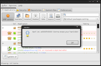
One of the nice things about Sabayon is that the kernel updating is quiet simple, given the complexities involved with the kernel. Below I outline a general procedure to help avoid any headaches one might have when updating their kernel.
1. Grab a list of drivers that will need to be updated:
2. Download/Install the kernel:
3. Install all packages listed in Step 1 (make sure to remove the version info otherwise you will just reinstall the current outdated package)
4. Verify that the kernel is selected:
5. If the new kernel is not selected with '*', set it with:
6. Also make sure opengl has the correct driver selected with:
7. Correct the opengl selection as needed with:
8. Make the new kernel the default option in grub (if so desired) by going to /boot/grub/menu.lst
9. Inside menu.lst change "default" to the the corresponding option.
10. It is also a good idea to run a dependency test and library test with:
And you should be good to go...NOT SO DIFFICULT IS IT?

One of the nice things about Sabayon is that the kernel updating is quiet simple, given the complexities involved with the kernel. Below I outline a general procedure to help avoid any headaches one might have when updating their kernel.
1. Grab a list of drivers that will need to be updated:
#equo query installed $(uname -r)
2. Download/Install the kernel:
#equo install sys-kernel/linux-sabayon
3. Install all packages listed in Step 1 (make sure to remove the version info otherwise you will just reinstall the current outdated package)
4. Verify that the kernel is selected:
#eselect kernel list
5. If the new kernel is not selected with '*', set it with:
#eselect kernel set [NUMBER]
6. Also make sure opengl has the correct driver selected with:
#eselect opengl list
7. Correct the opengl selection as needed with:
#eselect opengl set [NUMBER]
8. Make the new kernel the default option in grub (if so desired) by going to /boot/grub/menu.lst
9. Inside menu.lst change "default" to the the corresponding option.
10. It is also a good idea to run a dependency test and library test with:
#equo deptest
#equo libtest
And you should be good to go...NOT SO DIFFICULT IS IT?
Thursday, February 4, 2010
Setting up OpenCV in Eclipse on Windows
IF YOU ARE INSTALLING OPENCV VERSION 2.2 OR LATER PLEASE GO HERE INSTEAD: OpenCV 2.2 GUIDE.
First download and setup the basics:
- Get MinGW
- Download Eclipse C/C++ IDE
Note: I have a tutorial on these two steps already so just head over HERE for more info.
- Next download/install OpenCV 2.0 (OR download a more recent version)
- Now launch Eclipse and start a new project by going to:
- File->New->C++ Project (or File->New->C Project)
- Give your project a name in the "Project name" box
- Select the "Hello World" option under the "Project Type" section under the "Executable" folder. I recommend this over the "Empty Project" as it creates the c/c++ file for you instead of having to do it manually (it also creates a "src" folder and a "Debug" folder which helps keep things a little more organized)
- Make sure the "MinGW" Toolchain is selected in the "Toolchains" section
- Hit NEXT
- Fill in your Author and other file information, then hit NEXT
- In the next window select "Advanced settings...". This will bring you to the "Project Settings" which can always be accessed later by going to Project->Properties
- Under the "C/C++ Build" Section go to the "Settings" and select the "Tool Settings" Tab. Then select the "Includes" folder (on older versions of eclipse it is the "Directories" folder) in the GCC Compiler branch and add the opencv include directory to Include paths (-I): "C:\OpenCV2.0\include\opencv\". Of course, change C:\OpenCV2.0 to match the installed path that you used.
- Now, under the MinGW Linker select the "Libraries" folder and add the following to the Libraries (-l) section (note not all of these are necessarily needed for your project but these are all the libraries available in opencv):
- cv200
- cvaux200
- cxcore200
- cxts200
- highgui200
- ml200
In most cases you will only need cv200 and highgui200 to get started
ALSO NOTE: Versions 2.0 and later postfix the libraries names with a three digit number that corresponds to the version of OpenCV that you are linking to. Example: OpenCV2.1's highgui library must be linked using the name highgui210.
FINALLY, under the "Library search path (-L)" section add:
- "C:\OpenCV2.0\lib"
- Hit OK when done
- Hit Finish to create and start the Project
If you get an error, during compile time, pertaining to:
__exchange_and_add
Then visit this page and follow the instructions under:
Building on Windows using MinGW 3.4.5
Hope this helps!
Subscribe to:
Posts (Atom)