Here are the schematics:
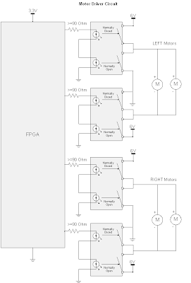
The "Motor Driver Circuit", does what it sounds like...it drives the motors; this circuit is used to interface the FPGA logic with the motors. Since the motors demand a significant amount of current to drive them (much more than the FPGA can provide), relays were used to create an interface between the logic and the motors which allows the motors to operate at full speed. Each side (left and right) are individually controlled via two SPDT relays. The relays used below are actually Dual SPST optical relays, but they can easily be wired up for SPDT operation. The NC (normally closed) state pushes 6V through the positive motor terminal which then goes to ground. The NO (normally open) state pushes 6V through the negative terminal which then goes to ground. An alternative H-Bridge Integrated Circuit could have been used to drive the motors; at the time of designing this circuit, I did not know of H-Bridges...but it turns out that is exactly what I designed! Catch Diodes may also be used to allow for additional protection and efficiency (but really are not needed in this implementation). Catch Diodes allow for a path for the electromagnetic field stored in an induction motor to deplete. These catch diodes are usually "schottky diodes" which are fast switching, low forward voltage diodes. These diodes are placed across each switching mechanism (i.e. transistor) in reverse bias configuration.

The "Collision Avoidance Circuit" is used to sense objects that are in close proximity and then steer away from the object. Infrared Proximity Sensors are used to acquire an analog voltage signal that is compared to a reference voltage that acts as the decision making device. These two IR sensors are mounted in front of the robot and are used to steer left or right. The third comparator in the circuit (in the middle), is used to make a decision as to which sensor detects a closer object. This third comparator will allow the robot to make an intelligent decision as to which way it should turn if a person or some non stationary object gets close to the robot.
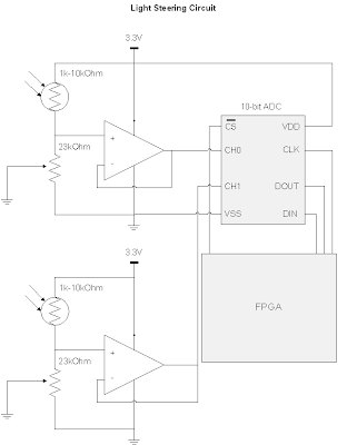
 The "Light Steering Circuit" is used to give the robot an objective other than avoiding collisions. When there are no objects being detected by the IR sensors, the Light Steering Circuit kicks in and guides the robot to locations containing high light intensity. In the future, I hope to addon to this robot and have a rechargable battery that is being powered by a photovoltaic cell. This circuit uses simple photocells to measure the light intensity. Again the robot uses stereoscopy to determine direction. A 10-bit ADC that communicates with the FPGA via the SPI (Serial Parallel Interface) protocol is used. The ADC wants a low impedance input, but doing so would cause problems with the photocell's voltage divider circuit being loaded down (effectively bypassing the 23K Ohm potentiometer), this means we need a buffer to create an intermediate stage that has a high input impedance and low output impedance.
The parts used are:
KNJN XYLO-LM FPGA board (used as the logic/brains of my robot). This is an EXPENSIVE piece of hardware, and I would NOT RECOMMEND getting this if you want to build a similar robot. There are much cheaper chips out there (i.e. PICS or even just a bunch of logic gates with a 555 timer chip) that can do the same thing this is doing. The only reason why I used an FPGA was because I already had the board and wanted to start another project with it.
http://www.knjn.com/ShopBoards_USB2.html
Mini Photocells (two of these are used in stereo to find the most intense lighting)
http://www.sparkfun.com/commerce/product_info.php?products_id=9088
10bit Analog-Digital Converter MCP3002 (used to acquire samples from the photocells)
http://dl.dropbox.com/u/767596/Resources/ROBO/21294C.pdf
I needed this 10-bit ADC versus a comparator because I wanted the robot to maintain going in a certain direction until there was a significant difference between the two photocells, otherwise the robot would constantly be turning left and right. This "difference parameter" is defined in my FPGA code. Eventually, I want to control this parameter through a Rotary encoder (which is basically a digital POT).
LM339 Quad Comparators (used as the decision making device for the obstacle avoidance system)
http://www.radioshack.com/product/index.jsp?productId=2062593
LM358 OpAmp (used to buffer the photocell signal, and make a high input impedance, low output impedance stage that goes into the 10bit ADC)
http://dl.dropbox.com/u/767596/Resources/ROBO/LM358.pdf
3.3 Voltage Regulator (used to power my FPGA board and some other components that want 3.3V instead of the 6V from my battery pack)
http://dl.dropbox.com/u/767596/Resources/ROBO/LD1117V33.pdf
Sharp IR Proximity Sensors (used to avoid obstacles by using two of them in stereo, and also used two additional sensors, one points down at the rear end and one pointing down at the front to avoid falling down a ledge)
http://dl.dropbox.com/u/767596/Resources/ROBO/GP2Y0A21YK.pdf
What's interesting about this sensor is the Voltage vs. Distance curve. Since the peak output voltage is at 6cm or so, and it drops off both as you increase and decrease in distance, I was able to split this curve into two sections. The 0-6cm range is used as the "drop-off detection" where I used the logic: if the distance is less than X cm away keep the motors in the default state, otherwise go into reverse. The 6-80cm range was used for the "object-avoidance circuit" that helped steer the robot when an object was in a defined range.
Wheel Encoders (used to track the wheel rotations, not actually implemented into my design yet)
http://www.sparkfun.com/commerce/product_info.php?products_id=9208
Micro Metal Gearmotor 100:1 (I use 4 of these motors, which enables the robot to have enough torque to go on carpet)
http://www.sparkfun.com/commerce/product_info.php?products_id=8910
SPDT Relay Switches (These are photo relay switches, so they don't even make the clicking noise. I use these to drive the motors from the 6V and GND supplies. I use 6V-->GND for the forward drive and the GND-->6V for the reverse drive)
http://dl.dropbox.com/u/767596/Resources/ROBO/ps7122a1c.pdf
Pictures, videos, and HDL code to come later!
No comments:
Post a Comment