Monday, September 28, 2009

Matlab's Find Function

Throughout my entire undergraduate studies at UNH there was a great deal of interaction with MATLAB; however, I was never exposed to one of the nicest functions in MATLAB until grad school. The function I am referring to is:

find


Find, is a very powerful function that can be used to help you search for certain elements in an array. Lets start off with a practical application of "find". Suppose you have a voltage signal that is stored in two arrays. The first array contains all the sampled voltages (lets call this array vArray) and the second array contains the timing information (lets call this array tArray). Suppose we want to determine where all the zero-crossings are in the signal and then pull the corresponding timing information from it. Just follow this code:


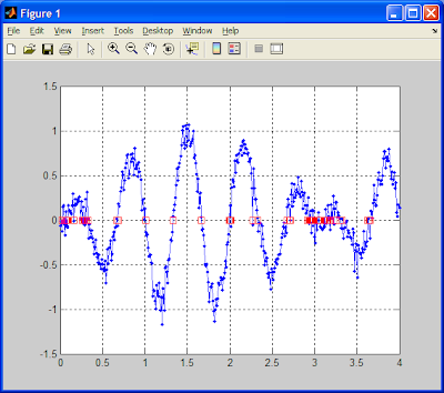
And Here is a plot of the Results


As you can see, I detected every zero crossing point in the signal. Now if this was a real system, I probably wouldn't want to detect the zero crossings with the noise that I have; in which case I would want to apply a low-pass filter of some sort that restricts the detection to the intended signal, but that is out of the scope of this topic.

Now it's your turn to play around with "find".

Matlab Performance Benchmarking

Matlab has a lot of interesting little functions/programs that you will come to discover along the way. One of the interesting functions that matlab has is an evaluation timer. By using the "tic" and "toc" commands, you can get an idea of where your inefficiencies are in your coding. I learned about this feature during a course I took in my graduate studies called Introduction to Neural Networks. Neural Networks are a very process intensive and it is important to be as efficient as possible if you want to have some sort of practical application. In neural networks it is common to see algorithms displayed in two forms: iterative/looping or vector-matrix form. I was playing around with these two forms and was interested in how one method performed over the other so I started search for a way to benchmark my functions; thats when I came across tic-toc. I already knew Matlab was particularly friendly with matrix operations versus looping operations but I wanted to quantify that speculation.

tic
CODE HERE
toc

By encapsulating your code between tic and toc Matlab can output a timer that keeps track of how long it took to evaluate that segment of code. Try it out for yourself and you might find some better methodologies for coding in Matlab.

Also, if you are just looking to benchmark your computers performance try:

bench

Tuesday, September 22, 2009

Xilinx Chipscope

Chipscope is an excellent tool for debugging your HDL code. Unlike the simulation tools that attempt to simulate the hardware, Chipscope is code that is physically implemented in your FPGA. This allows you to physically and precisely examine the functionality of your code. Note: This is not available in the WebPack (free version) of ISE.


To use chipscope you will need to first create your chipscope cores:
1. Create a new coregen core
-- If you make a subfolder for the cores (say in a folder called "coregen" in the project directory) make sure to use the command:
--- -sd ./coregen
--- Place this command in the Command Line Options under the Synthesize properties as well as the Implement properties
--- This tells ISE to look in the subfolder called "coregen" for missing cores/modules
2. Now make the "ila" core and the "icon" core inside coregen
3. Add these cores to your project. The files to add will either be .v or .vhd depending on you language preference.
4. Next you will need to instantiate them inside your module/architecture
-- If you are using VHDL, you should just be able to instantiate the icon and ila after the "begin" statement in the architecture design.
-- If you are using Verilog, your safest bet is to instantiate it at the end of the module before the "endmodule" statement
-- Here is an example of instantiation of the icon and ila in verilog:

//Wires used to map the IOs of the ila and icon
//to the current module

//The control mechanism between the icon and ila.
//Just leave this alone
wire [35:0] chipscope_control;

//The data you will be monitoring.
//These bits can be distributed among many
//variables in your design
wire [31:0] chipscope_data;

//An optional trigger. If left unassigned,
//chipscope will by default start acquiring
//instantly and stop once memory has filled.
//I.e. you might want to trigger on a
//pushbutton switch.
wire [7:0] chipscope_trig;
chipscope_ila_v1_02_a ila(
//internal control between ila and icon
.CONTROL(chipscope_control),

//The clock that chipscope will run at
.CLK(clk),

//The data chipscope will monitor
.DATA(chipscope_data),

//The event chipscope will trigger on.
.TRIG0(chipscope_trig));
chipscope_icon_v1_03_a icon(
//Internal control between ila and icon
.CONTROL0(chipscope_control) );

These instantiations can be found inside the core's .v and .vhd files. You just need to worry about the wire/signals you want to use locally in your module.

Enjoy.

Xilinx iMPACT

So you have finished your HDL coding and generated the bit file, but now you need to write that file to your FPGA; your next step is to get familiar with iMPACT.

iMPACT is Xilinx's method of programming their FPGAs through a JTAG interface. Most of the time you will need a JTAG to serial/parallel/usb cable. These are generally expensive (approx. $100-200) but are not necessarily required. Check with your boards documentation on what is needed to program it. Most likely if it doesn't need one of these cables, they will have their own tool that you should use.


Loading up iMPACT

1. When you load up iMPACT it will prompt you create or load a new project
2. If this is your first time you will want to create a new project
3. Many people don't save this project and just create a new one each time it opens. Its up to you how you want to handle this.
4. The next screen relates to detecting the device at hand
5. You should make sure your board is connected to the computer and powered up before going any further.
6. Generally you should select the Boundary-Scan option. This will scan the common interfaces for your board.
7. After the scan has been completed you will see your FPGA part number show up in the program window.
8. The next screen(s) will prompt you for the .bit

Monday, September 14, 2009

HDL Functions

If you need to create a function in HDL you're in luck, cause I had to learn it myself last week. And lucky for me it was very simple.

In my particular case I was using an enumerated signal type and I needed to convert that signal back to a std_logic_vector signal such that I could output that signal for debugging purposes. Below is the code I used to convert two enumerated inputs to a single logic vector signal. Notice that the syntax is very similar to "process" definitions. The only key difference is the "return" declaration after the function declaration. This return declaration only requires the data type. It does not need to know what size the vector is (if it is a vector). This is nice since it potentially allows the user to have variable sized inputs...although I have not tried this myself, so it might not be synthesize-able.

function enum2std_logic(
arg1:STATE_TYPE;
arg2:SUBSTATE_TYPE)
return std_logic_vector is
variable val: std_logic_vector(3 downto 0);
begin
case arg1 is
when IDLE =>
val(3 downto 1):="000";
when READ1 =>
val(3 downto 1):="001";
when READ2 =>
val(3 downto 1):="010";
when WRITE1 =>
val(3 downto 1):="011";
when WRITE2 =>
val(3 downto 1):="100";
when others =>
val(3 downto 1):="000";
end case;
case arg2 is
when Processing =>
val(0):='0';
when Waiting =>
val(0):='1';
end case;
return val;
end function enum2std_logic;

Hope this helps.

HDL Enumerations

If you are like me and have trouble remembering what bits correspond to what setting or action in your code then enumerated types are your best friend.

To create an enumerated type just follow this syntax:
type STATE_TYPE is (IDLE, READ1, READ2, WRITE1, WRITE2);
attribute ENUM_ENCODING: STRING;
attribute ENUM_ENCODING of STATE_TYPE:type is "000 001 010 011 100";

This creates a data type called STATE_TYPE that contains the enumerations: IDLE, READ1, READ2, WRITE1, WRITE2

These enumerations use the following encoding respectively: 000, 001, 010, 011, 100

All you have to do to create a signal that uses such an enumerated type is specify STATE_TYPE (or whatever you choose to call it) as the data type in your signal declaration.

Hope this helps.

HDL Statemachines

Often times in HDL programming we need to describe what is know as a statemachine. For those unfamiliar with what statemachines are please refer to:
Finite-State-Machines

State machines require the use of both combinational logic and registers. The registers are used to hold the state variable information that is required to make the decision in the "next" clock cycle. The combinatorial logic is used to set the criteria for transitioning from one state to the next.

In this article I will show an example of how you might choose to implement a statemachine. This is not necessarily the best or most efficient way to implement one, but it is the way that I found easiest to understand.

If you have been following my HDL articles up to this point you probably noticed that I have only shown an architecture containing a single process. In the case of a statemachine, you must have at least 2 processes defined.
  • One process controls the updating of the state variables
  • One process handles the logic and navigation to the "next" state
Suppose we have a system that requires the use of a statemachine that contains two states, 0 and 1, which are mapped to a signal called "state". Also, suppose a logic variable that is used to navigate from one state to the next is define as "input" which can also take on the value of 0 or 1. Finally, lets suppose the logic that this statemachine follows is:

If state=0
If input=0
stay in state 0
Else
go to state 1
End if;
Else
If input=1
state in state 1
Else
go to state 0
End if;
End if;


To create this system using a statemachine is quite simple. First lets create the state update process:

update_states: process (clk)
begin
if(clk'EVENT and clk='1') then
current_state<=next_state; end if; end process;


The process above uses 3 signals.
  1. clk = This is the clk to the system, and in this case we are operating on the positive edge of the clock; however, you can make it operate on whatever part of the clock signal you wish.
  2. current_state = This is the current state we are in. This is to be used in the combinational logic.
  3. next_state = This is the next state that we will transition to in our statemachine.
You might be wondering, why do we have two state variables when you clearly defined having just one?

First, think of a REAL system that operates on clock edges; lets just say we have 2 casscaded positive edge triggered D-Flip Flops. What happens when you try to grab a value at the output of the first flip flop (which is the input to the second flip flop) and simultaneously try to write a new value at the input to 2nd flip flop?

The problem is, trying to simulateously read and write on a signal (or line) is undeterministic. We must remember that HDL uses concurrency, so we don't know whether the read or the write operation occurred first. Because of this, we must define two signals, one which is used to indicate the current state, that we can use to "read" from, and we define another signal that indicates the next state, that we can "write" to.

Now that we have our update_states process defined we can now work on the logic. In this example our logic is VERY simple.


    state_machine: process (clk)
    begin
    if(clk'EVENT and clk='1') then
    if (current_state='0') then
    if (input='0')
    next_state<=next_state; else next_state<='1'; end if; else if (input='1') next_state<=next_state; else next_state<='0'; end if; end if; end if; end process;


    And there you have it...your two processes that make the simple statemachine we defined. Of course, for this to work in an actual design, you will need to define the clk, current_state, next_state, and input signals. Which I am sure you can do if you read my previous tutorials.